
Logic gate:
- Logic gate is an electronic circuit that is used to take logical decisions based on the input.
- It contains one or more number of inputs and one output.
- The working of logic gate is based on the binary principle that has two states either logic 0 or logic 1.
- The output of logic gate is produced when it satisfies any of its logic conditions.
- The logic condition depends upon the type of the gates and the number of inputs.
- The primary logic gates include AND, OR and NOT and the combinations of these gates are used to implement any of the other logic gates.
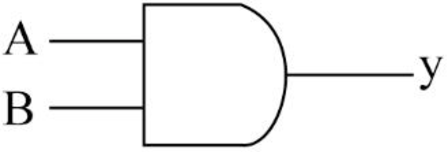
AND gate:
- The AND gate refers to a logic gate whose output will be HIGH only when all the inputs are HIGH.
- The output of AND gate will be LOW when any one of its input is LOW.
- The symbol to represent AND gate is given below:
- The truth table for AND gate is as follows:
| INPUT A | INPUT B | OUTPUT Y |
| 0 | 0 | 0 |
| 0 | 1 | 0 |
| 1 | 0 | 0 |
| 1 | 1 | 1 |
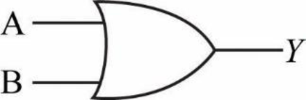
OR gate:
- The OR gate refers to a logic gate whose output will be HIGH when any one of its inputs are HIGH.
- The output of AND gate will be LOW when both the inputs are LOW.
- The symbol to represent OR gate is given below:
- The truth table for OR gate is as follows:
| INPUT A | INPUT B | OUTPUT Y |
| 0 | 0 | 0 |
| 0 | 1 | 1 |
| 1 | 0 | 1 |
| 1 | 1 | 1 |
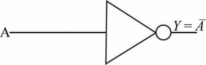
NOT gate:
- The NOT gate refers to a logic gate whose output will be HIGH when it’s input is LOW and whose output will be LOW when it’s input is HIGH.
- The symbol to represent NOT gate is given below:
- The truth table for NOT gate is as follows:
| INPUT A | OUTPUT Y |
| 0 | 1 |
| 1 | 0 |
Explanation of Solution
b.
Logic gate circuit:
The logic gate circuit for the given Boolean expression
Explanation:
In the above given logic gate circuit,
- The inputs “A” and “B” are connected to logic AND gate and the corresponding output will be (AB)
Explanation of Solution
c.
Logic gate circuit:
The logic gate circuit for the given Boolean expression
Explanation:
In the above given logic gate circuit,
- The inputs “A” and “B” are connected to logic OR gate and the corresponding output will be (A+B).
- The input “C” is connected to logic NOT gate and the corresponding output will be “
Explanation of Solution
d.
Logic gate circuit:
The logic gate circuit for the given Boolean expression
Explanation:
In the above given logic gate circuit,
- The inputs “C” and “D” are connected to logic AND gate and the corresponding output will be (CD).
- Now, the resultant along with other input “B” is connected to logic OR gate whose output will be
Explanation of Solution
e.
Logic gate circuit:
The logic gate circuit for the given Boolean expression
Explanation:
In the above given logic gate circuit,
- The input “A” is connected to logic NOT gate and the corresponding output will be “
Explanation of Solution
f.
Logic gate circuit:
The logic gate circuit for the given Boolean expression
Explanation:
In the above given logic gate circuit,
- The inputs “A”, “B” and “C” are connected to logic AND gate and the corresponding output will be (ABC).
- Now, the resultant along with the other input “D” is connected to logic OR gate whose output will be

Trending nowThis is a popular solution!

Chapter 4 Solutions
Programmable Logic Controllers

- Lab 07: Java Graphics (Bonus lab) In this lab, we'll be practicing what we learned about GUIs, and Mouse events. You will need to implement the following: ➤ A GUI with a drawing panel. We can click in this panel, and you will capture those clicks as a Point (see java.awt.Point) in a PointCollection class (you need to build this). о The points need to be represented by circles. Below the drawing panel, you will need 5 buttons: о An input button to register your mouse to the drawing panel. ○ о о A show button to paint the points in your collection on the drawing panel. A button to shift all the points to the left by 50 pixels. The x position of the points is not allowed to go below zero. Another button to shift all the points to the right 50 pixels. The x position of the points cannot go further than the You can implement this GUI in any way you choose. I suggest using the BorderLayout for a panel containing the buttons, and a GridLayout to hold the drawing panel and button panels.…arrow_forwardIf a UDP datagram is sent from host A, port P to host B, port Q, but at host B there is no process listening to port Q, then B is to send back an ICMP Port Unreachable message to A. Like all ICMP messages, this is addressed to A as a whole, not to port P on A. (a) Give an example of when an application might want to receive such ICMP messages. (b) Find out what an application has to do, on the operating system of your choice, to receive such messages. (c) Why might it not be a good idea to send such messages directly back to the originating port P on A?arrow_forwardDiscuss how business intelligence and data visualization work together to help decision-makers and data users. Provide 2 specific use cases.arrow_forward
- This week we will be building a regression model conceptually for our discussion assignment. Consider your current workplace (or previous/future workplace if not currently working) and answer the following set of questions. Expand where needed to help others understand your thinking: What is the most important factor (variable) that needs to be predicted accurately at work? Why? Justify its selection as your dependent variable.arrow_forwardAccording to best practices, you should always make a copy of a config file and add a date to filename before editing? Explain why this should be done and what could be the pitfalls of not doing it.arrow_forwardIn completing this report, you may be required to rely heavily on principles relevant, for example, the Work System, Managerial and Functional Levels, Information and International Systems, and Security. apply Problem Solving Techniques (Think Outside The Box) when completing. should reflect relevance, clarity, and organisation based on research. Your research must be demonstrated by Details from the scenario to support your analysis, Theories from your readings, Three or more scholarly references are required from books, UWIlinc, etc, in-text or narrated citations of at least four (4) references. “Implementation of an Integrated Inventory Management System at Green Fields Manufacturing” Green Fields Manufacturing is a mid-sized company specialising in eco-friendly home and garden products. In recent years, growing demand has exposed the limitations of their fragmented processes and outdated systems. Different departments manage production schedules, raw material requirements, and…arrow_forward
- 1. Create a Book record that implements the Comparable interface, comparing the Book objects by year - title: String > - author: String - year: int Book + compareTo(other Book: Book): int + toString(): String Submit your source code on Canvas (Copy your code to text box or upload.java file) > Comparable 2. Create a main method in Book record. 1) In the main method, create an array of 2 objects of Book with your choice of title, author, and year. 2) Sort the array by year 3) Print the object. Override the toString in Book to match the example output: @Javadoc Declaration Console X Properties Book [Java Application] /Users/kuan/.p2/pool/plugins/org.eclipse.justj.openjdk.hotspo [Book: year=1901, Book: year=2010]arrow_forwardQ5-The efficiency of a 200 KVA, single phase transformer is 98% when operating at full load 0.8 lagging p.f. the iron losses in the transformer is 2000 watt. Calculate the i) Full load copper losses ii) half load copper losses and efficiency at half load. Ans: 1265.306 watt, 97.186%arrow_forward2. Consider the following pseudocode for partition: function partition (A,L,R) pivotkey = A [R] t = L for i L to R-1 inclusive: if A[i] A[i] t = t + 1 end if end for A [t] A[R] return t end function Suppose we call partition (A,0,5) on A=[10,1,9,2,8,5]. Show the state of the list at the indicated instances. Initial A After i=0 ends After 1 ends After i 2 ends After i = 3 ends After i = 4 ends After final swap 10 19 285 [12 pts]arrow_forward
- .NET Interactive Solving Sudoku using Grover's Algorithm We will now solve a simple problem using Grover's algorithm, for which we do not necessarily know the solution beforehand. Our problem is a 2x2 binary sudoku, which in our case has two simple rules: •No column may contain the same value twice •No row may contain the same value twice If we assign each square in our sudoku to a variable like so: 1 V V₁ V3 V2 we want our circuit to output a solution to this sudoku. Note that, while this approach of using Grover's algorithm to solve this problem is not practical (you can probably find the solution in your head!), the purpose of this example is to demonstrate the conversion of classical decision problems into oracles for Grover's algorithm. Turning the Problem into a Circuit We want to create an oracle that will help us solve this problem, and we will start by creating a circuit that identifies a correct solution, we simply need to create a classical function on a quantum circuit that…arrow_forwardusing r languagearrow_forward8. Cash RegisterThis exercise assumes you have created the RetailItem class for Programming Exercise 5. Create a CashRegister class that can be used with the RetailItem class. The CashRegister class should be able to internally keep a list of RetailItem objects. The class should have the following methods: A method named purchase_item that accepts a RetailItem object as an argument. Each time the purchase_item method is called, the RetailItem object that is passed as an argument should be added to the list. A method named get_total that returns the total price of all the RetailItem objects stored in the CashRegister object’s internal list. A method named show_items that displays data about the RetailItem objects stored in the CashRegister object’s internal list. A method named clear that should clear the CashRegister object’s internal list. Demonstrate the CashRegister class in a program that allows the user to select several items for purchase. When the user is ready to check out, the…arrow_forward
 Programming Logic & Design ComprehensiveComputer ScienceISBN:9781337669405Author:FARRELLPublisher:Cengage
 Systems ArchitectureComputer ScienceISBN:9781305080195Author:Stephen D. BurdPublisher:Cengage Learning
 Operations Research : Applications and AlgorithmsComputer ScienceISBN:9780534380588Author:Wayne L. WinstonPublisher:Brooks Cole
 C++ for Engineers and ScientistsComputer ScienceISBN:9781133187844Author:Bronson, Gary J.Publisher:Course Technology Ptr
 Principles of Information Systems (MindTap Course...Computer ScienceISBN:9781285867168Author:Ralph Stair, George ReynoldsPublisher:Cengage Learning
 Fundamentals of Information SystemsComputer ScienceISBN:9781337097536Author:Ralph Stair, George ReynoldsPublisher:Cengage Learning