
Concept explainers
Logic gate:
- Logic gate is an electronic circuit that is used to take logical decisions based on the input.
- It contains one or more number of inputs and one output.
- The working of logic gate is based on the binary principle that has two states either logic 0 or logic 1.
- The output of logic gate is produced when it satisfies any of its logic conditions.
- The logic condition depends upon the type of the gates and the number of inputs.
- The primary logic gates include AND, OR and NOT and the combinations of these gates are used to implement any of the other logic gates.
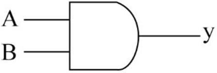
AND gate:
- The AND gate refers to a logic gate whose output will be HIGH only when all the inputs are HIGH.
- The output of AND gate will be LOW when any one of its input is LOW.
- The symbol to represent AND gate is given below.
- The truth table for AND gate is as follows.
| INPUT A | INPUT B | OUTPUT Y |
| 0 | 0 | 0 |
| 0 | 1 | 0 |
| 1 | 0 | 0 |
| 1 | 1 | 1 |
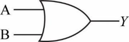
OR gate:
- The OR gate refers to a logic gate whose output will be HIGH when any one of its inputs are HIGH.
- The output of AND gate will be LOW when both the inputs are LOW.
- The symbol to represent OR gate is given below.
- The truth table for OR gate is as follows.
| INPUT A | INPUT B | OUTPUT Y |
| 0 | 0 | 0 |
| 0 | 1 | 1 |
| 1 | 0 | 1 |
| 1 | 1 | 1 |
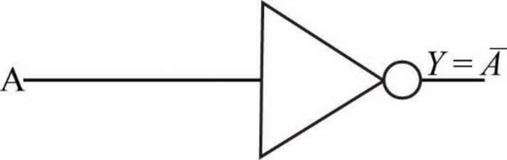
NOT gate:
- The NOT gate refers to a logic gate whose output will be HIGH when it’s input is LOW and whose output will be LOW when it’s input is HIGH.
- The symbol to represent NOT gate is given below.
- The truth table for NOT gate is as follows.
| INPUT A | OUTPUT Y |
| 0 | 1 |
| 1 | 0 |
Explanation of Solution
a.
Logic gate circuit:
The logic gate circuit is as follows.
Explanation:
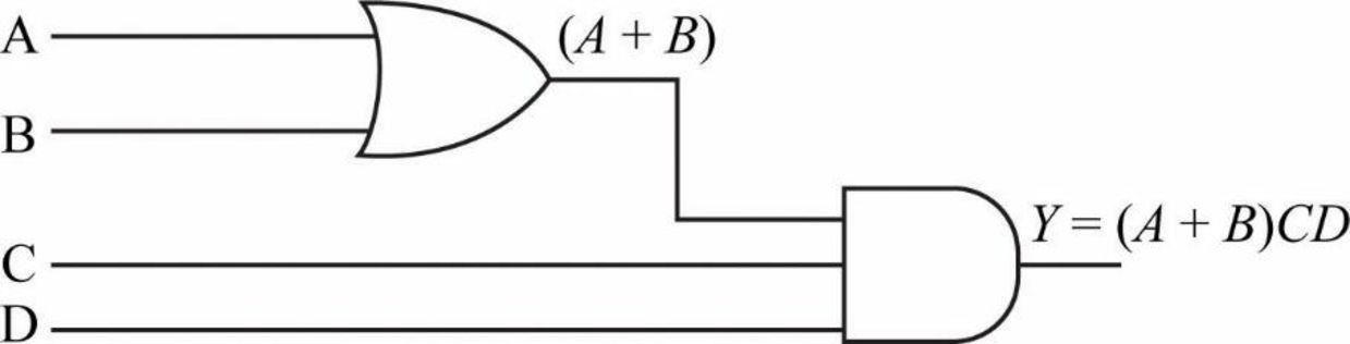
In the above given logic gate circuit,
- The inputs “A” and “B” are connected to logic OR gate and the corresponding output will be (A+B).
- Now, the resultant along with other inputs “C” and “D” are connected to logic AND gate whose output will be
Therefore, the Boolean expression for the given logic circuit is
Explanation of Solution
b.
Logic gate circuit:
The logic gate circuit is as follows.
Explanation:
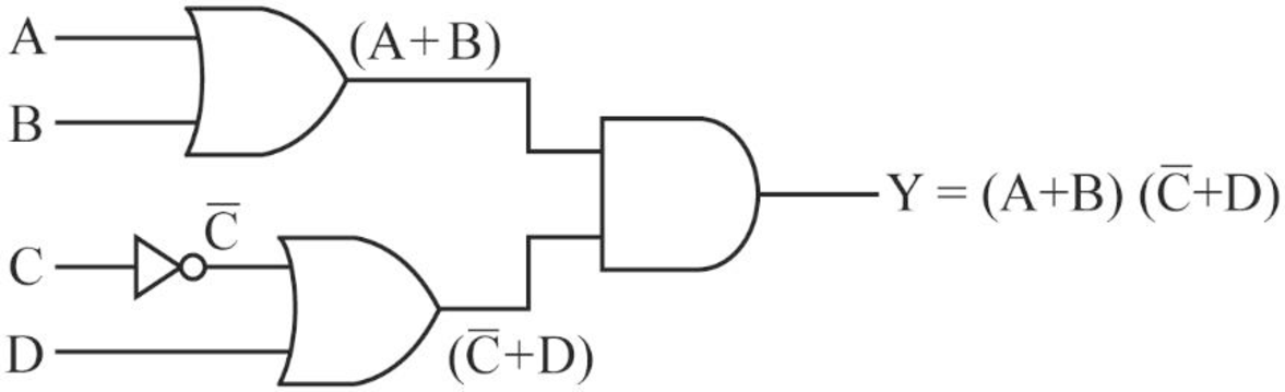
In the above given logic gate circuit,
- The inputs “A” and “B” are connected to logic OR gate and the corresponding output will be (A+B).
- The input “C” is connected to logic NOT gate and the corresponding output will be “
- Then, the inputs “
- Now, the output (A+B) and
Therefore, the Boolean expression for the given logic circuit is
Explanation of Solution
c.
Logic gate circuit:
The logic gate circuit is as follows.
Explanation:
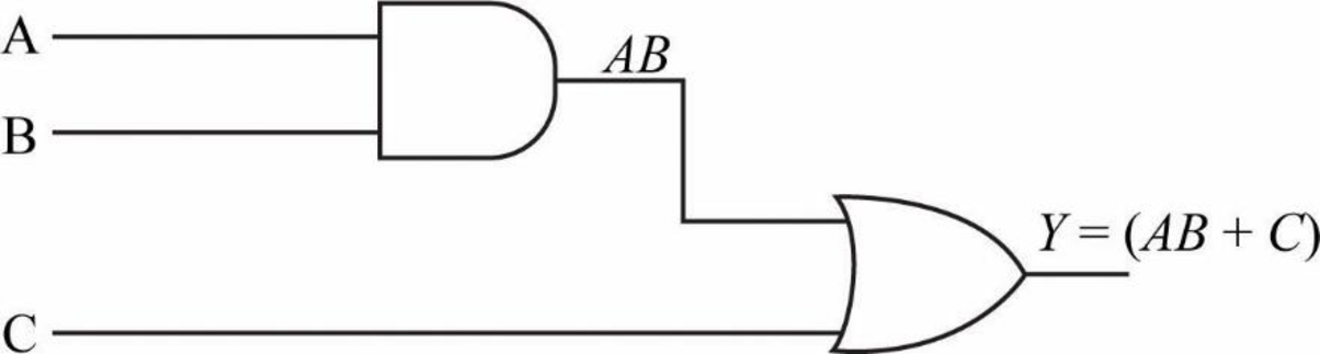
In the above given logic gate circuit,
- The inputs “A” and “B” are connected to logic AND gate and the corresponding output will be (AB).
- Now, the resultant along with other input “C” is connected to logic OR gate whose output will be
Therefore, the Boolean expression for the given logic circuit is
Explanation of Solution
d.
Logic gate circuit:
The logic gate circuit is as follows.
Explanation:
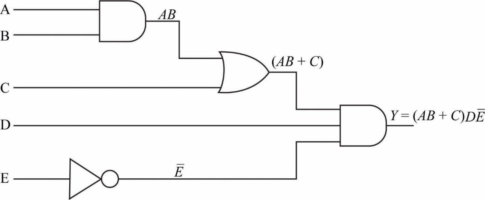
In the above given logic gate circuit,
- The inputs “A” and “B” are connected to logic AND gate and the corresponding output will be (AB).
- Now, the resultant along with other input “C” is connected to logic OR gate whose output will be
- The input “E” is connected to logic NOT gate and the corresponding output will be “
- Now, the outputs
Therefore, the Boolean expression for the given logic circuit is
Explanation of Solution
e.
Logic gate circuit:
The logic gate circuit is as follows.
Explanation:
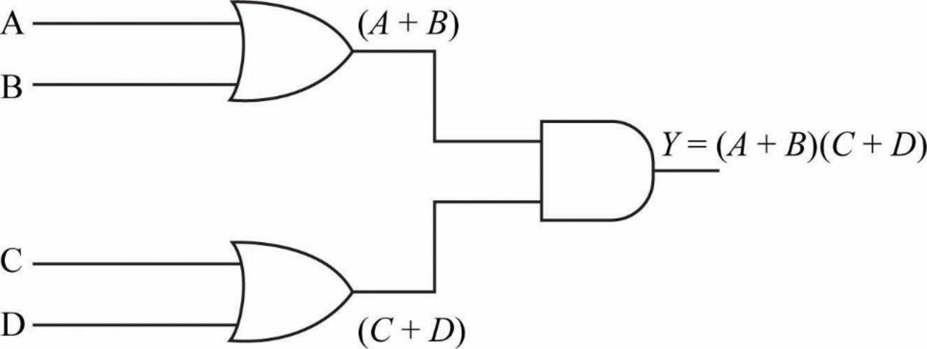
In the above given logic gate circuit,
- The inputs “A” and “B” are connected to logic OR gate and the corresponding output will be (A+B).
- Then, the inputs “C” and “D” are connected to logic OR gate and the corresponding output will be
- Now, the output (A+B) and
Therefore, the Boolean expression for the given logic circuit is
Explanation of Solution
f.
Logic gate circuit:
The logic gate circuit is as follows.
Explanation:
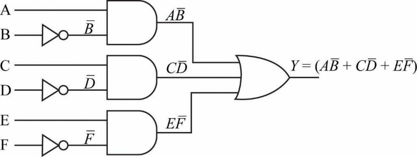
In the above given logic gate circuit,
- The input “B” is connected to logic NOT gate and the corresponding output will be “
- The inputs “A” and “
- Similarly, the input “D” is connected to logic NOT gate and the corresponding output will be “
- The inputs “C” and “
- Then, the input “F” is connected to logic NOT gate and the corresponding output will be “
- The inputs “E” and “
- Finally, the outputs
Therefore, the Boolean expression for the given logic circuit is
Want to see more full solutions like this?
Chapter 4 Solutions
Programmable Logic Controllers


 Systems ArchitectureComputer ScienceISBN:9781305080195Author:Stephen D. BurdPublisher:Cengage Learning
 Operations Research : Applications and AlgorithmsComputer ScienceISBN:9780534380588Author:Wayne L. WinstonPublisher:Brooks Cole
 Programming Logic & Design ComprehensiveComputer ScienceISBN:9781337669405Author:FARRELLPublisher:Cengage
 EBK JAVA PROGRAMMINGComputer ScienceISBN:9781305480537Author:FARRELLPublisher:CENGAGE LEARNING - CONSIGNMENT
 Principles of Information Systems (MindTap Course...Computer ScienceISBN:9781285867168Author:Ralph Stair, George ReynoldsPublisher:Cengage Learning
 C++ for Engineers and ScientistsComputer ScienceISBN:9781133187844Author:Bronson, Gary J.Publisher:Course Technology Ptr