
Programmable Logic Controllers
5th Edition
ISBN: 9780073373843
Author: Frank D. Petruzella
Publisher: McGraw-Hill Education
expand_more
expand_more
format_list_bulleted
Concept explainers
Question
Chapter 4, Problem 5RQ
Program Plan Intro
Logic gate:
- Logic gate is an electronic circuit that is used to take logical decisions based on the input.
- It contains one or more number of inputs and one output.
- The working of logic gate is based on the binary principle that has two states either logic 0 or logic 1.
- The output of logic gate is produced when it satisfies any of its logic conditions.
- The logic condition depends upon the type of the gates and the number of inputs.
- The primary logic gates include AND, OR and NOT and the combinations of these gates are used to implement any of the other logic gates.
AND gate:
- The AND gate refers to a logic gate whose output will be HIGH only when all the inputs are HIGH.
- The output of AND gate will be LOW when any one of its input is LOW.
- The symbol to represent AND gate is given below:
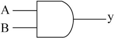
- The truth table for AND gate is as follows:
| INPUT A | INPUT B | OUTPUT Y |
| 0 | 0 | 0 |
| 0 | 1 | 0 |
| 1 | 0 | 0 |
| 1 | 1 | 1 |
OR gate:
- The OR gate refers to a logic gate whose output will be HIGH when any one of its inputs are HIGH.
- The output of AND gate will be LOW when both the inputs are LOW.
- The symbol to represent OR gate is given below:
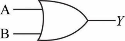
- The truth table for OR gate is as follows:
| INPUT A | INPUT B | OUTPUT Y |
| 0 | 0 | 0 |
| 0 | 1 | 1 |
| 1 | 0 | 1 |
| 1 | 1 | 1 |
NOT gate:
- The NOT gate refers to a logic gate whose output will be HIGH when it’s input is LOW and whose output will be LOW when it’s input is HIGH.
- The symbol to represent NOT gate is given below:
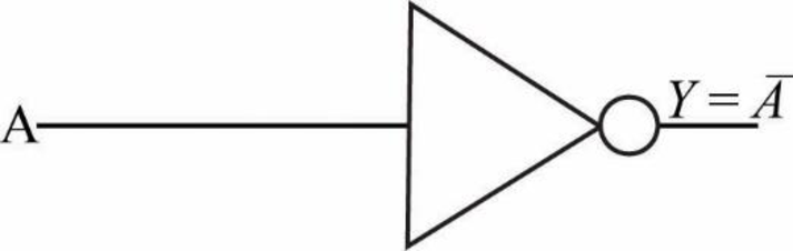
- The truth table for NOT gate is as follows:
| INPUT A | OUTPUT Y |
| 0 | 1 |
| 1 | 0 |
Explanation of Solution
b.
Logic gate circuit:
The logic gate circuit for the given relay ladder diagram is as follows.
Explanation:
In the above given logic gate circuit,
- The input “C” is connected to logic NOT gate and the corresponding output will be “
- Then the inputs “A”, “B”, “
- Now, the resultant along with the other input “D” is connected to a logic AND gate whose output will be
Expert Solution & Answer
Want to see the full answer?
Check out a sample textbook solution
Students have asked these similar questions
Need help with this in python!
Need help with this in python!
Help! How do I turn the flowchart that searches for a name in an array of names into structured and spaced pseudocode?
Chapter 4 Solutions
Programmable Logic Controllers
Knowledge Booster


Learn more about
Need a deep-dive on the concept behind this application? Look no further. Learn more about this topic, computer-science and related others by exploring similar questions and additional content below.Similar questions
- The mail merge process has ____ steps. Question 19Select one: a. five b. six c. seven d. eightarrow_forwardIf you created a main document based on an existing document entitled "Confirmation Letter," what default filename would Word give the main document? Question 14Select one: a. Confirmation Letter-1 b. Confirmation Letter-merge c. Document1 d. MergedDocument1arrow_forwardClick the ____ option button in the Mail Merge task pane to use an Outlook contact list as a data source for a merge. Question 11Select one: a. Use Outlook contacts list b. Select from Outlook contacts c. Select Contacts d. Mail Merge Recipientsarrow_forward
- A(n) ____ cannot be selected as the document type in the Mail Merge task pane. Question 9Select one: a. Letter b. Directory c. Fax d. E-mail messagearrow_forwardConsider a Superstore Database which consists of 3 tables, Orders, Returns, and Managers. The CSV files have been provided along with this DOC file in the Midterm 2 Link in the Moodle. Answer the questions as below: Use the created table as in the provided SQL query file, solve the problems as mentioned below. You will have to import the respective CSV files of the above created tables as without them, it is impossible to solve the questions below. If you are not able to upload the files successfully, do not leave the query questions. Just write the query to the best of your knowledge. Do not copy. To be graded for the screenshot answer, you must upload the CSV properly and paste the resulting screenshot of the queries as asked. Write Query to Find out which Product Sub-Category has a sum of Shipping Cost to sum of Sales ratio > 0.03.arrow_forwardI need to render an image of a car continuously for a smooth visual experience in C# WinForms. It gets the location array (that has all the x,y of the tiles it should visit) from another function - assume it is already written.arrow_forward
- write c program with features: Register a Bunny: Store the bunny's name, poem, and initialize the egg count to 0. Modify an Entry: Change the bunny's poem or update the egg count. Delete a Bunny: Remove a registered bunny from the list. List All Bunnies: Display all registered bunnies and their details. Save & Load Data: Store bunny data in a file to persist between runs. Use a struct to represent a bunny contestant. Store data in a binary file (bunnies.dat) for persistence. Use file I/O functions (fopen, fwrite, fread, etc.) to manage data. Implement a menu-driven interface for user interaction.arrow_forwardHelp, how do I write the pseudocode for the findMean function and flowchart for this?arrow_forwardNeed help drawing a flowchart for the findMax function herearrow_forward
- Need help writing the pseudocode for the findMin function with attachedarrow_forwardCreate a static function in C# where poachers appear and attempt to hunt animals. It gets the location of the closest animal to itself. Take account of that the animal also move too, so it should update the closest location (x, y) everytime it moves to a new location. Use winforms to show the movements of poachers.arrow_forwardCreate a static function in C# where poachers appear and attempt to hunt animals. It gets the location of the closest animal to itself. Take account of that the animal also moves too, so it should update the closest location (x, y) everytime it moves to a new location. Use winforms to show to movementsarrow_forward
arrow_back_ios
SEE MORE QUESTIONS
arrow_forward_ios
Recommended textbooks for you
 Programming Logic & Design ComprehensiveComputer ScienceISBN:9781337669405Author:FARRELLPublisher:Cengage
 Systems ArchitectureComputer ScienceISBN:9781305080195Author:Stephen D. BurdPublisher:Cengage Learning
 Operations Research : Applications and AlgorithmsComputer ScienceISBN:9780534380588Author:Wayne L. WinstonPublisher:Brooks Cole
 C++ for Engineers and ScientistsComputer ScienceISBN:9781133187844Author:Bronson, Gary J.Publisher:Course Technology Ptr
 Principles of Information Systems (MindTap Course...Computer ScienceISBN:9781285867168Author:Ralph Stair, George ReynoldsPublisher:Cengage Learning
Programming Logic & Design Comprehensive
Computer Science
ISBN:9781337669405
Author:FARRELL
Publisher:Cengage
Systems Architecture
Computer Science
ISBN:9781305080195
Author:Stephen D. Burd
Publisher:Cengage Learning
Operations Research : Applications and Algorithms
Computer Science
ISBN:9780534380588
Author:Wayne L. Winston
Publisher:Brooks Cole
C++ for Engineers and Scientists
Computer Science
ISBN:9781133187844
Author:Bronson, Gary J.
Publisher:Course Technology Ptr
Principles of Information Systems (MindTap Course...
Computer Science
ISBN:9781285867168
Author:Ralph Stair, George Reynolds
Publisher:Cengage Learning