
Applied Fluid Mechanics (7th Edition)
7th Edition
ISBN: 9780132558921
Author: Robert L. Mott, Joseph A. Untener
Publisher: PEARSON
expand_more
expand_more
format_list_bulleted
Videos
Textbook Question
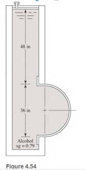
Chapter 4, Problem 4.54PP
Use Fig. 4.54. The surface is
Expert Solution & Answer
Want to see the full answer?
Check out a sample textbook solution
Students have asked these similar questions
3.) 15.40 – Collar B moves up at constant velocity vB = 1.5 m/s. Rod AB has length = 1.2 m. The incline is
at angle = 25°. Compute an expression for the angular velocity of rod AB, ė and the velocity of end A of the
rod (✓✓) as a function of v₂,1,0,0. Then compute numerical answers for ȧ & y_ with 0 = 50°.
2.) 15.12 The assembly shown consists of the straight rod ABC which passes through and is welded to the
grectangular plate DEFH. The assembly rotates about the axis AC with a constant angular velocity of 9 rad/s.
Knowing that the motion when viewed from C is counterclockwise, determine the velocity and acceleration of
corner F.
500
Q3: The attachment shown in Fig.3 is made of
1040 HR. The static force is 30 kN. Specify the
weldment (give the pattern, electrode
number, type of weld, length of weld, and leg
size).
Fig. 3
All dimension
in mm
30 kN
100
(10 Marks)
Chapter 4 Solutions
Applied Fluid Mechanics (7th Edition)
Ch. 4 - figure 4.2 shows a vacuum tank with a flat...Ch. 4 - The flat left end of the tank shown in Fig. 4.21...Ch. 4 - An exhaust system for a room creates a partial...Ch. 4 - A piece of 14 -in Schedule 40 pipe is used as a...Ch. 4 - A pressure relief valve is designed so that the...Ch. 4 - A gas-powered cannon shoots projectiles by...Ch. 4 - The egress hatch of a manned spacecraft is...Ch. 4 - A tank containing liquid ammonia at 77F has a flat...Ch. 4 - The bottom of a laboratory vat has a hole in it to...Ch. 4 - A simple shower for remote locations is designed...
Ch. 4 - Calculate the total force on the bottom of the...Ch. 4 - If the length of the tank in Fig. 4.24 is 1.2m,...Ch. 4 - An observation port in a small submarine is...Ch. 4 - A rectangular gate is installed in a vertical wall...Ch. 4 - '4.15 A vat has a sloped side, as shown in Fig....Ch. 4 - The wall shown in Fig. 4.28 is 20 ft long, (a)...Ch. 4 - If the wall in Fig. 4.29 is 4m long, calculate the...Ch. 4 - Refer to Fig. 4.30Ch. 4 - Refer to Fig. 4.31Ch. 4 - Refer to Fig.4.32Ch. 4 - Refer to Fig 4.33Ch. 4 - Refer to Fig. 4.34Ch. 4 - Refer to Fig. 4.35 (?Ch. 4 - Swimming poo!WilierGlasswindow2 ft diameterFigure...Ch. 4 - 4.25 Refer to Fig 4.37Ch. 4 - Refer to Fig.4.38Ch. 4 - Refer to Fig.4.39Ch. 4 - Refer to Fig.4.40Ch. 4 - Refer to Fig 4.41Ch. 4 - figure 4.42i5 shows a gasoline tank filled into...Ch. 4 - If the tank in Fig. 4.42 is filled just to the...Ch. 4 - If the tank in Fig. 4.42 is only half full of...Ch. 4 - For the water tank shown in Fig. 4.43, compute the...Ch. 4 - For the water tank shown in Fig. 4.43, compute the...Ch. 4 - For the water tank shown in Fig. 4.43, compute the...Ch. 4 - For the orange-drink tank shown in Fig. 4.32,...Ch. 4 - For the orange-drink tank shown in Fig. 4.32,...Ch. 4 - For the oil tank shown in Fig. 4.35, compute the...Ch. 4 - For the oil tank shown in Fig. 4.35; compute the...Ch. 4 - figure 4.44 shows a rectangular gate holding water...Ch. 4 - figure 4.45 shows a gate hinged at its bottom and...Ch. 4 - figure 4.46 shows a tank of water with a circular...Ch. 4 - Repeat Problem 4.19(Fig. 4.31), except that the...Ch. 4 - Repeat Problem 4.22 (Fig. 4.32), except that the...Ch. 4 - Repeat Problem 4.26 (Fig. 4.38 ). except that the...Ch. 4 - Repeat Problem 4.28 (Fig. 4.40 ), except that the...Ch. 4 - Use Fig 4.47. The surface is 2.00m long.Ch. 4 - Use Fig.4.48. The surface is 2.50m long.Ch. 4 - Use Fig.4.49. The surface is 5.00 ft longCh. 4 - Use Fig.4.50. The surface is 4.50 ft long.Ch. 4 - Use Fig.4.51.The surface is 4.00 m long.Ch. 4 - Use Fig .4.52. The surface is 1.50m longCh. 4 - Use Fig. 4.53. The surface is 1.50m long.Ch. 4 - Use Fig. 4.54. The surface is 60 in longCh. 4 - Repeat Problem 4.47 using Fig. 4.47, except that...Ch. 4 - Repeat Problem 4.48 using Fig. 4.48, except that...Ch. 4 - The tank in Fig. 4.55 has a view port in the...Ch. 4 - Insulated concrete forms (ICFs) are becoming more...Ch. 4 - Lacks are installed in rivers to allow boats to...Ch. 4 - When a dam is installed in a river that has...Ch. 4 - A wealthy eccentric is interested in having an...Ch. 4 - A pneumatic cylinder like the one shown in Fig....Ch. 4 - Determine the magnitude and the location of the...Ch. 4 - For the hinged gate shown in Fig. 4.61, determine...Ch. 4 - Prob. 4.65PPCh. 4 - Write a program to solve Problem 4.41 with any...Ch. 4 - Write a program to solve Problem 4.42 (Fig. 4.46)...Ch. 4 - Write a program to solve curved surface problems...Ch. 4 - For Program 1, cause the depth h to vary over some...
Additional Engineering Textbook Solutions
Find more solutions based on key concepts
Using your text editor, enter (that is, type in) the C++ program shown in Display 1.8. Be certain to type the f...
Problem Solving with C++ (10th Edition)
How are relationships between tables expressed in a relational database?
Modern Database Management
This optional Google account security feature sends you a message with a code that you must enter, in addition ...
SURVEY OF OPERATING SYSTEMS
What types of coolant are used in vehicles?
Automotive Technology: Principles, Diagnosis, And Service (6th Edition) (halderman Automotive Series)
17–1C A high-speed aircraft is cruising in still air. How does the temperature of air at the nose of the aircra...
Thermodynamics: An Engineering Approach
What is an uninitialized variable?
Starting Out with Programming Logic and Design (5th Edition) (What's New in Computer Science)
Knowledge Booster


Learn more about
Need a deep-dive on the concept behind this application? Look no further. Learn more about this topic, mechanical-engineering and related others by exploring similar questions and additional content below.Similar questions
- (read image) (answer given)arrow_forwardA cylinder and a disk are used as pulleys, as shown in the figure. Using the data given in the figure, if a body of mass m = 3 kg is released from rest after falling a height h 1.5 m, find: a) The velocity of the body. b) The angular velocity of the disk. c) The number of revolutions the cylinder has made. T₁ F Rd = 0.2 m md = 2 kg T T₂1 Rc = 0.4 m mc = 5 kg ☐ m = 3 kgarrow_forward(read image) (answer given)arrow_forward
- 11-5. Compute all the dimensional changes for the steel bar when subjected to the loads shown. The proportional limit of the steel is 230 MPa. 265 kN 100 mm 600 kN 25 mm thickness X Z 600 kN 450 mm E=207×103 MPa; μ= 0.25 265 kNarrow_forwardT₁ F Rd = 0.2 m md = 2 kg T₂ Tz1 Rc = 0.4 m mc = 5 kg m = 3 kgarrow_forward2. Find a basis of solutions by the Frobenius method. Try to identify the series as expansions of known functions. (x + 2)²y" + (x + 2)y' - y = 0 ; Hint: Let: z = x+2arrow_forward
- 1. Find a power series solution in powers of x. y" - y' + x²y = 0arrow_forward3. Find a basis of solutions by the Frobenius method. Try to identify the series as expansions of known functions. 8x2y" +10xy' + (x 1)y = 0 -arrow_forwardHello I was going over the solution for this probem and I'm a bit confused on the last part. Can you please explain to me 1^4 was used for the Co of the tubular cross section? Thank you!arrow_forward
- Blood (HD = 0.45 in large diameter tubes) is forced through hollow fiber tubes that are 20 µm in diameter.Equating the volumetric flowrate expressions from (1) assuming marginal zone theory and (2) using an apparentviscosity for the blood, estimate the marginal zone thickness at this diameter. The viscosity of plasma is 1.2 cParrow_forwardQ2: Find the shear load on bolt A for the connection shown in Figure 2. Dimensions are in mm Fig. 2 24 0-0 0-0 A 180kN (10 Markarrow_forwarddetermine the direction and magnitude of angular velocity ω3 of link CD in the four-bar linkage using the relative velocity graphical methodarrow_forward
arrow_back_ios
SEE MORE QUESTIONS
arrow_forward_ios
Recommended textbooks for you
 International Edition---engineering Mechanics: St...Mechanical EngineeringISBN:9781305501607Author:Andrew Pytel And Jaan KiusalaasPublisher:CENGAGE L
International Edition---engineering Mechanics: St...
Mechanical Engineering
ISBN:9781305501607
Author:Andrew Pytel And Jaan Kiusalaas
Publisher:CENGAGE L
Physics 33 - Fluid Statics (1 of 10) Pressure in a Fluid; Author: Michel van Biezen;https://www.youtube.com/watch?v=mzjlAla3H1Q;License: Standard YouTube License, CC-BY