
Applied Fluid Mechanics (7th Edition)
7th Edition
ISBN: 9780132558921
Author: Robert L. Mott, Joseph A. Untener
Publisher: PEARSON
expand_more
expand_more
format_list_bulleted
Videos
Textbook Question
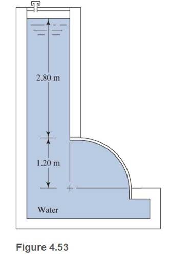
Chapter 4, Problem 4.53PP
Use Fig. 4.53. The surface is
Expert Solution & Answer
Want to see the full answer?
Check out a sample textbook solution
Students have asked these similar questions
11-19
designed
in Problem
The shaft shown in figure P11-4 was
10-19, for the data in the row(s) assigned from table
PII-1, and the corresponding diameter of shaft found
in Problem 10-19, design suitable bearings
5 E8 cycles at
the load for at least
State all assumptions.
to support
1200rpm.
(a) Using hydrodynamically lubricated bronze sleeve
bearings with ON = 40, Lld = 0.8, and clearance ratio
0.0025.
of
a
← gear
T
gear
Key
figure PI-4
Given
from the problem
10-19 we get d= 1.153 in
from the table 11-1 we get
a = 16 in
b= 18in
L= 20in
In an irrigation system, the following characteristics of the pipe network are available.• 100 meters of 4" PVC pipe, 3 gate valves• 500 meters of 3" PVC pipe, 4 gate valves• 200 meters of 2" H.G. pipe, 2 globe valves• 50 litres per second circulate in the pipes:Calculate:1. Total energy losses in meters.2. Leaks in pipes.3. Losses in accessories.4. Calculate the equivalent pipe of that system assuming only pipes without fittings.Solve the problem without artificial intelligence, solve by one of the experts
In a series pipe, calculate the diameter 2 according to the following:• Ltotal: 325 m• L1: 52 m, D1: 3/4"• L2: 254 m, D2:?• L3: 19 m, D: 1-1/4".Indicate the nominal diameter.
Solve without using artificial inteligence, solve by one of the experts
Chapter 4 Solutions
Applied Fluid Mechanics (7th Edition)
Ch. 4 - figure 4.2 shows a vacuum tank with a flat...Ch. 4 - The flat left end of the tank shown in Fig. 4.21...Ch. 4 - An exhaust system for a room creates a partial...Ch. 4 - A piece of 14 -in Schedule 40 pipe is used as a...Ch. 4 - A pressure relief valve is designed so that the...Ch. 4 - A gas-powered cannon shoots projectiles by...Ch. 4 - The egress hatch of a manned spacecraft is...Ch. 4 - A tank containing liquid ammonia at 77F has a flat...Ch. 4 - The bottom of a laboratory vat has a hole in it to...Ch. 4 - A simple shower for remote locations is designed...
Ch. 4 - Calculate the total force on the bottom of the...Ch. 4 - If the length of the tank in Fig. 4.24 is 1.2m,...Ch. 4 - An observation port in a small submarine is...Ch. 4 - A rectangular gate is installed in a vertical wall...Ch. 4 - '4.15 A vat has a sloped side, as shown in Fig....Ch. 4 - The wall shown in Fig. 4.28 is 20 ft long, (a)...Ch. 4 - If the wall in Fig. 4.29 is 4m long, calculate the...Ch. 4 - Refer to Fig. 4.30Ch. 4 - Refer to Fig. 4.31Ch. 4 - Refer to Fig.4.32Ch. 4 - Refer to Fig 4.33Ch. 4 - Refer to Fig. 4.34Ch. 4 - Refer to Fig. 4.35 (?Ch. 4 - Swimming poo!WilierGlasswindow2 ft diameterFigure...Ch. 4 - 4.25 Refer to Fig 4.37Ch. 4 - Refer to Fig.4.38Ch. 4 - Refer to Fig.4.39Ch. 4 - Refer to Fig.4.40Ch. 4 - Refer to Fig 4.41Ch. 4 - figure 4.42i5 shows a gasoline tank filled into...Ch. 4 - If the tank in Fig. 4.42 is filled just to the...Ch. 4 - If the tank in Fig. 4.42 is only half full of...Ch. 4 - For the water tank shown in Fig. 4.43, compute the...Ch. 4 - For the water tank shown in Fig. 4.43, compute the...Ch. 4 - For the water tank shown in Fig. 4.43, compute the...Ch. 4 - For the orange-drink tank shown in Fig. 4.32,...Ch. 4 - For the orange-drink tank shown in Fig. 4.32,...Ch. 4 - For the oil tank shown in Fig. 4.35, compute the...Ch. 4 - For the oil tank shown in Fig. 4.35; compute the...Ch. 4 - figure 4.44 shows a rectangular gate holding water...Ch. 4 - figure 4.45 shows a gate hinged at its bottom and...Ch. 4 - figure 4.46 shows a tank of water with a circular...Ch. 4 - Repeat Problem 4.19(Fig. 4.31), except that the...Ch. 4 - Repeat Problem 4.22 (Fig. 4.32), except that the...Ch. 4 - Repeat Problem 4.26 (Fig. 4.38 ). except that the...Ch. 4 - Repeat Problem 4.28 (Fig. 4.40 ), except that the...Ch. 4 - Use Fig 4.47. The surface is 2.00m long.Ch. 4 - Use Fig.4.48. The surface is 2.50m long.Ch. 4 - Use Fig.4.49. The surface is 5.00 ft longCh. 4 - Use Fig.4.50. The surface is 4.50 ft long.Ch. 4 - Use Fig.4.51.The surface is 4.00 m long.Ch. 4 - Use Fig .4.52. The surface is 1.50m longCh. 4 - Use Fig. 4.53. The surface is 1.50m long.Ch. 4 - Use Fig. 4.54. The surface is 60 in longCh. 4 - Repeat Problem 4.47 using Fig. 4.47, except that...Ch. 4 - Repeat Problem 4.48 using Fig. 4.48, except that...Ch. 4 - The tank in Fig. 4.55 has a view port in the...Ch. 4 - Insulated concrete forms (ICFs) are becoming more...Ch. 4 - Lacks are installed in rivers to allow boats to...Ch. 4 - When a dam is installed in a river that has...Ch. 4 - A wealthy eccentric is interested in having an...Ch. 4 - A pneumatic cylinder like the one shown in Fig....Ch. 4 - Determine the magnitude and the location of the...Ch. 4 - For the hinged gate shown in Fig. 4.61, determine...Ch. 4 - Prob. 4.65PPCh. 4 - Write a program to solve Problem 4.41 with any...Ch. 4 - Write a program to solve Problem 4.42 (Fig. 4.46)...Ch. 4 - Write a program to solve curved surface problems...Ch. 4 - For Program 1, cause the depth h to vary over some...
Additional Engineering Textbook Solutions
Find more solutions based on key concepts
Consider the following C program void fun (void) { int a, b, c; / defiinition.1 / . . . while (. . .) int b, c,...
Concepts Of Programming Languages
What are some of the ways by which a polymer extrusion is rapidly cooled?
Degarmo's Materials And Processes In Manufacturing
Write an SQL statement to display the last name, first name, and email of any owners of cats. Use a subquery.
Database Concepts (8th Edition)
What is a ToolTip?
Starting Out With Visual Basic (8th Edition)
Roman Numerals Write a program that prompts the user to enter a number within the range of 1 through 10. The pr...
Starting Out with Java: From Control Structures through Objects (7th Edition) (What's New in Computer Science)
Describe the difference between the while loop and the do-while loop.
Starting Out with Java: From Control Structures through Data Structures (4th Edition) (What's New in Computer Science)
Knowledge Booster


Learn more about
Need a deep-dive on the concept behind this application? Look no further. Learn more about this topic, mechanical-engineering and related others by exploring similar questions and additional content below.Similar questions
- What is the critical speed of the shaft in rad/s for one, two, and three elements?arrow_forward2. Express the following complex numbers in rectangular form. (a) z₁ = 2еjл/6 (b) Z2=-3e-jπ/4 (c) Z3 = √√√3e-j³/4 (d) z4 = − j³arrow_forwardA prismatic beam is built into a structure. You can consider the boundary conditions at A and B to be fixed supports. The beam was originally designed to withstand a triangular distributed load, however, the loading condition has been revised and can be approximated by a cosine function as shown in the figure below. You have been tasked with analysing the structure. As the beam is prismatic, you can assume that the bending rigidity (El) is constant. wwo cos 2L x A B Figure 3: Built in beam with a varying distributed load In order to do this, you will: a. Solve the reaction forces and moments at point A and B. Hint: you may find it convenient to use the principal of superposition. (2%) b. Plot the shear force and bending moment diagrams and identify the maximum shear force and bending moment. (2%) c. Develop an expression for the vertical deflection. Clearly state your expression in terms of x. (1%)arrow_forward
- Question 1: Beam Analysis Two beams (ABC and CD) are connected using a pin immediately to the left of Point C. The pin acts as a moment release, i.e. no moments are transferred through this pinned connection. Shear forces can be transferred through the pinned connection. Beam ABC has a pinned support at point A and a roller support at Point C. Beam CD has a roller support at Point D. A concentrated load, P, is applied to the mid span of beam CD, and acts at an angle as shown below. Two concentrated moments, MB and Mc act in the directions shown at Point B and Point C respectively. The magnitude of these moments is PL. Moment Release A B с ° MB = PL Mc= = PL -L/2- -L/2- → P D Figure 1: Two beam arrangement for question 1. To analyse this structure, you will: a) Construct the free body diagrams for the structure shown above. When constructing your FBD's you must make section cuts at point B and C. You can represent the structure as three separate beams. Following this, construct the…arrow_forwardA cantilevered rectangular prismatic beam has three loads applied. 10,000N in the positive x direction, 500N in the positive z direction and 750 in the negative y direction. You have been tasked with analysing the stresses at three points on the beam, a, b and c. 32mm 60mm 24mm 180mm 15mm 15mm 40mm 750N 16mm 500N x 10,000N Figure 2: Idealisation of the structure and the applied loading (right). Photograph of the new product (left). Picture sourced from amazon.com.au. To assess the design, you will: a) Determine state of stress at all points (a, b and c). These points are located on the exterior surface of the beam. Point a is located along the centreline of the beam, point b is 15mm from the centreline and point c is located on the edge of the beam. When calculating the stresses you must consider the stresses due to bending and transverse shear. Present your results in a table and ensure that your sign convention is clearly shown (and applied consistently!) (3%) b) You have identified…arrow_forward7.82 Water flows from the reservoir on the left to the reservoir on the right at a rate of 16 cfs. The formula for the head losses in the pipes is h₁ = 0.02(L/D)(V²/2g). What elevation in the left reservoir is required to produce this flow? Also carefully sketch the HGL and the EGL for the system. Note: Assume the head-loss formula can be used for the smaller pipe as well as for the larger pipe. Assume α = 1.0 at all locations. Elevation = ? 200 ft 300 ft D₁ = 1.128 ft D2=1.596 ft 12 2012 Problem 7.82 Elevation = 110 ftarrow_forward
- Homework#5arrow_forwardA closed-cycle gas turbine unit operating with maximum and minimum temperature of 760oC and 20oC has a pressure ratio of 7/1. Calculate the ideal cycle efficiency and the work ratioarrow_forwardConsider a steam power plant that operates on a simple, ideal Rankine cycle and has a net power output of 45 MW. Steam enters the turbine at 7 MPa and 500°C and is cooled in the condenser at a pressure of 10 kPa by running cooling water from a lake through the tubes of the condenser at a rate of 2000 kg/s. Show the cycle on a T-s diagram with respect to saturation lines, and determine The thermal efficiency of the cycle,The mass flow rate of the steam and the temperature rise of the cooling waterarrow_forwardTwo reversible heat engines operate in series between a source at 600°C, and a sink at 30°C. If the engines have equal efficiencies and the first rejects 400 kJ to the second, calculate: the temperature at which heat is supplied to the second engine, The heat taken from the source; and The work done by each engine. Assume each engine operates on the Carnot cyclearrow_forwardA steam turbine operates at steady state with inlet conditions of P1 = 5 bar, T1 = 320°C. Steam leaves the turbine at a pressure of 1 bar. There is no significant heat transfer between the turbine and its surroundings, and kinetic and potential energy changes between inlet and exit are negligible. If the isentropic turbine efficiency is 75%, determine the work developed per unit mass of steam flowing through the turbine, in kJ/kgarrow_forwardHomework#5arrow_forwardarrow_back_iosSEE MORE QUESTIONSarrow_forward_iosRecommended textbooks for you
 International Edition---engineering Mechanics: St...Mechanical EngineeringISBN:9781305501607Author:Andrew Pytel And Jaan KiusalaasPublisher:CENGAGE L
International Edition---engineering Mechanics: St...Mechanical EngineeringISBN:9781305501607Author:Andrew Pytel And Jaan KiusalaasPublisher:CENGAGE L
Physics 33 - Fluid Statics (1 of 10) Pressure in a Fluid; Author: Michel van Biezen;https://www.youtube.com/watch?v=mzjlAla3H1Q;License: Standard YouTube License, CC-BY