
Applied Fluid Mechanics (7th Edition)
7th Edition
ISBN: 9780132558921
Author: Robert L. Mott, Joseph A. Untener
Publisher: PEARSON
expand_more
expand_more
format_list_bulleted
Concept explainers
Videos
Textbook Question
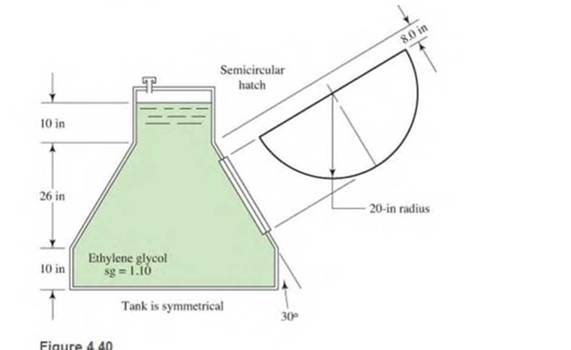
Chapter 4, Problem 4.28PP
Refer to Fig.4.40
Expert Solution & Answer
Want to see the full answer?
Check out a sample textbook solution
Students have asked these similar questions
Problem (17): water flowing in an open channel of a rectangular cross-section with width (b) transitions from a
mild slope to a steep slope (i.e., from subcritical to supercritical flow) with normal water depths of (y₁) and
(y2), respectively.
Given the values of y₁ [m], y₂ [m], and b [m], calculate the discharge in the channel (Q) in [Lit/s].
Givens:
y1 = 4.112 m
y2 =
0.387 m
b = 0.942 m
Answers:
( 1 ) 1880.186 lit/s
( 2 ) 4042.945 lit/s
( 3 ) 2553.11 lit/s
( 4 ) 3130.448 lit/s
Problem (14): A pump is being used to lift water from an underground
tank through a pipe of diameter (d) at discharge (Q). The total head
loss until the pump entrance can be calculated as (h₁ = K[V²/2g]), h
where (V) is the flow velocity in the pipe. The elevation difference
between the pump and tank surface is (h).
Given the values of h [cm], d [cm], and K [-], calculate the maximum
discharge Q [Lit/s] beyond which cavitation would take place at the
pump entrance. Assume Turbulent flow conditions.
Givens:
h = 120.31 cm
d = 14.455 cm
K = 8.976
Q
Answers:
(1) 94.917 lit/s
(2) 49.048 lit/s
( 3 ) 80.722 lit/s
68.588 lit/s
4
Problem (13): A pump is being used to lift water from the bottom
tank to the top tank in a galvanized iron pipe at a discharge (Q).
The length and diameter of the pipe section from the bottom tank
to the pump are (L₁) and (d₁), respectively. The length and
diameter of the pipe section from the pump to the top tank are
(L2) and (d2), respectively.
Given the values of Q [L/s], L₁ [m], d₁ [m], L₂ [m], d₂ [m],
calculate total head loss due to friction (i.e., major loss) in the
pipe (hmajor-loss) in [cm].
Givens:
L₁,d₁
Pump
L₂,d2
오
0.533 lit/s
L1 =
6920.729 m
d1 =
1.065 m
L2 =
70.946 m
d2
0.072 m
Answers:
(1)
3.069 cm
(2) 3.914 cm
( 3 ) 2.519 cm
( 4 ) 1.855 cm
TABLE 8.1
Equivalent Roughness for New Pipes
Pipe
Riveted steel
Concrete
Wood stave
Cast iron
Galvanized iron
Equivalent Roughness, &
Feet
Millimeters
0.003-0.03 0.9-9.0
0.001-0.01 0.3-3.0
0.0006-0.003 0.18-0.9
0.00085
0.26
0.0005
0.15
0.045
0.000005
0.0015
0.0 (smooth) 0.0 (smooth)
Commercial steel or wrought iron 0.00015
Drawn…
Chapter 4 Solutions
Applied Fluid Mechanics (7th Edition)
Ch. 4 - figure 4.2 shows a vacuum tank with a flat...Ch. 4 - The flat left end of the tank shown in Fig. 4.21...Ch. 4 - An exhaust system for a room creates a partial...Ch. 4 - A piece of 14 -in Schedule 40 pipe is used as a...Ch. 4 - A pressure relief valve is designed so that the...Ch. 4 - A gas-powered cannon shoots projectiles by...Ch. 4 - The egress hatch of a manned spacecraft is...Ch. 4 - A tank containing liquid ammonia at 77F has a flat...Ch. 4 - The bottom of a laboratory vat has a hole in it to...Ch. 4 - A simple shower for remote locations is designed...
Ch. 4 - Calculate the total force on the bottom of the...Ch. 4 - If the length of the tank in Fig. 4.24 is 1.2m,...Ch. 4 - An observation port in a small submarine is...Ch. 4 - A rectangular gate is installed in a vertical wall...Ch. 4 - '4.15 A vat has a sloped side, as shown in Fig....Ch. 4 - The wall shown in Fig. 4.28 is 20 ft long, (a)...Ch. 4 - If the wall in Fig. 4.29 is 4m long, calculate the...Ch. 4 - Refer to Fig. 4.30Ch. 4 - Refer to Fig. 4.31Ch. 4 - Refer to Fig.4.32Ch. 4 - Refer to Fig 4.33Ch. 4 - Refer to Fig. 4.34Ch. 4 - Refer to Fig. 4.35 (?Ch. 4 - Swimming poo!WilierGlasswindow2 ft diameterFigure...Ch. 4 - 4.25 Refer to Fig 4.37Ch. 4 - Refer to Fig.4.38Ch. 4 - Refer to Fig.4.39Ch. 4 - Refer to Fig.4.40Ch. 4 - Refer to Fig 4.41Ch. 4 - figure 4.42i5 shows a gasoline tank filled into...Ch. 4 - If the tank in Fig. 4.42 is filled just to the...Ch. 4 - If the tank in Fig. 4.42 is only half full of...Ch. 4 - For the water tank shown in Fig. 4.43, compute the...Ch. 4 - For the water tank shown in Fig. 4.43, compute the...Ch. 4 - For the water tank shown in Fig. 4.43, compute the...Ch. 4 - For the orange-drink tank shown in Fig. 4.32,...Ch. 4 - For the orange-drink tank shown in Fig. 4.32,...Ch. 4 - For the oil tank shown in Fig. 4.35, compute the...Ch. 4 - For the oil tank shown in Fig. 4.35; compute the...Ch. 4 - figure 4.44 shows a rectangular gate holding water...Ch. 4 - figure 4.45 shows a gate hinged at its bottom and...Ch. 4 - figure 4.46 shows a tank of water with a circular...Ch. 4 - Repeat Problem 4.19(Fig. 4.31), except that the...Ch. 4 - Repeat Problem 4.22 (Fig. 4.32), except that the...Ch. 4 - Repeat Problem 4.26 (Fig. 4.38 ). except that the...Ch. 4 - Repeat Problem 4.28 (Fig. 4.40 ), except that the...Ch. 4 - Use Fig 4.47. The surface is 2.00m long.Ch. 4 - Use Fig.4.48. The surface is 2.50m long.Ch. 4 - Use Fig.4.49. The surface is 5.00 ft longCh. 4 - Use Fig.4.50. The surface is 4.50 ft long.Ch. 4 - Use Fig.4.51.The surface is 4.00 m long.Ch. 4 - Use Fig .4.52. The surface is 1.50m longCh. 4 - Use Fig. 4.53. The surface is 1.50m long.Ch. 4 - Use Fig. 4.54. The surface is 60 in longCh. 4 - Repeat Problem 4.47 using Fig. 4.47, except that...Ch. 4 - Repeat Problem 4.48 using Fig. 4.48, except that...Ch. 4 - The tank in Fig. 4.55 has a view port in the...Ch. 4 - Insulated concrete forms (ICFs) are becoming more...Ch. 4 - Lacks are installed in rivers to allow boats to...Ch. 4 - When a dam is installed in a river that has...Ch. 4 - A wealthy eccentric is interested in having an...Ch. 4 - A pneumatic cylinder like the one shown in Fig....Ch. 4 - Determine the magnitude and the location of the...Ch. 4 - For the hinged gate shown in Fig. 4.61, determine...Ch. 4 - Prob. 4.65PPCh. 4 - Write a program to solve Problem 4.41 with any...Ch. 4 - Write a program to solve Problem 4.42 (Fig. 4.46)...Ch. 4 - Write a program to solve curved surface problems...Ch. 4 - For Program 1, cause the depth h to vary over some...
Knowledge Booster


Learn more about
Need a deep-dive on the concept behind this application? Look no further. Learn more about this topic, mechanical-engineering and related others by exploring similar questions and additional content below.Similar questions
- The flow rate is 12.275 Liters/s and the diameter is 6.266 cm.arrow_forwardAn experimental setup is being built to study the flow in a large water main (i.e., a large pipe). The water main is expected to convey a discharge (Qp). The experimental tube will be built at a length scale of 1/20 of the actual water main. After building the experimental setup, the pressure drop per unit length in the model tube (APm/Lm) is measured. Problem (20): Given the value of APm/Lm [kPa/m], and assuming pressure coefficient similitude, calculate the drop in the pressure per unit length of the water main (APP/Lp) in [Pa/m]. Givens: AP M/L m = 590.637 kPa/m meen Answers: ( 1 ) 59.369 Pa/m ( 2 ) 73.83 Pa/m (3) 95.443 Pa/m ( 4 ) 44.444 Pa/m *******arrow_forwardFind the reaction force in y if Ain = 0.169 m^2, Aout = 0.143 m^2, p_in = 0.552 atm, Q = 0.367 m^3/s, α = 31.72 degrees. The pipe is flat on the ground so do not factor in weight of the pipe and fluid.arrow_forward
- Find the reaction force in x if Ain = 0.301 m^2, Aout = 0.177 m^2, p_in = 1.338 atm, Q = 0.669 m^3/s, and α = 37.183 degreesarrow_forwardProblem 5: Three-Force Equilibrium A structural connection at point O is in equilibrium under the action of three forces. • • . Member A applies a force of 9 kN vertically upward along the y-axis. Member B applies an unknown force F at the angle shown. Member C applies an unknown force T along its length at an angle shown. Determine the magnitudes of forces F and T required for equilibrium, assuming 0 = 90° y 9 kN Aarrow_forwardProblem 19: Determine the force in members HG, HE, and DE of the truss, and state if the members are in tension or compression. 4 ft K J I H G B C D E F -3 ft -3 ft 3 ft 3 ft 3 ft- 1500 lb 1500 lb 1500 lb 1500 lb 1500 lbarrow_forward
- Problem 14: Determine the reactions at the pin A, and the tension in cord. Neglect the thickness of the beam. F1=26kN F2 13 12 80° -2m 3marrow_forwardProblem 22: Determine the force in members GF, FC, and CD of the bridge truss and state if the members are in tension or compression. F 15 ft B D -40 ft 40 ft -40 ft 40 ft- 5 k 10 k 15 k 30 ft Earrow_forwardProblem 20: Determine the force in members BC, HC, and HG. After the truss is sectioned use a single equation of equilibrium for the calculation of each force. State if the members are in tension or compression. 5 kN 4 kN 4 kN 3 kN 2 kN B D E F 3 m -5 m- -5 m- 5 m 5 m-arrow_forward
- An experimental setup is being built to study the flow in a large water main (i.e., a large pipe). The water main is expected to convey a discharge (Qp). The experimental tube will be built at a length scale of 1/20 of the actual water main. After building the experimental setup, the pressure drop per unit length in the model tube (APm/Lm) is measured. Problem (19): Given the value of Qp [m³/s], and assuming Reynolds number similitude between the water main and experimental tube, calculate the flow rate in the model tube (Qm) in [lit/s]. = 30.015 m^3/sarrow_forwardProblem 11: The lamp has a weight of 15 lb and is supported by the six cords connected together as shown. Determine the tension in each cord and the angle 0 for equilibrium. Cord BC is horizontal. E 30° B 60° Aarrow_forwardProblem 10: If the bucket weighs 50 lb, determine the tension developed in each of the wires. B $30° 5 E D 130°arrow_forward
arrow_back_ios
SEE MORE QUESTIONS
arrow_forward_ios
Recommended textbooks for you
 Elements Of ElectromagneticsMechanical EngineeringISBN:9780190698614Author:Sadiku, Matthew N. O.Publisher:Oxford University Press
 Mechanics of Materials (10th Edition)Mechanical EngineeringISBN:9780134319650Author:Russell C. HibbelerPublisher:PEARSON
 Thermodynamics: An Engineering ApproachMechanical EngineeringISBN:9781259822674Author:Yunus A. Cengel Dr., Michael A. BolesPublisher:McGraw-Hill Education
 Control Systems EngineeringMechanical EngineeringISBN:9781118170519Author:Norman S. NisePublisher:WILEY
 Mechanics of Materials (MindTap Course List)Mechanical EngineeringISBN:9781337093347Author:Barry J. Goodno, James M. GerePublisher:Cengage Learning
 Engineering Mechanics: StaticsMechanical EngineeringISBN:9781118807330Author:James L. Meriam, L. G. Kraige, J. N. BoltonPublisher:WILEY
Elements Of Electromagnetics
Mechanical Engineering
ISBN:9780190698614
Author:Sadiku, Matthew N. O.
Publisher:Oxford University Press
Mechanics of Materials (10th Edition)
Mechanical Engineering
ISBN:9780134319650
Author:Russell C. Hibbeler
Publisher:PEARSON
Thermodynamics: An Engineering Approach
Mechanical Engineering
ISBN:9781259822674
Author:Yunus A. Cengel Dr., Michael A. Boles
Publisher:McGraw-Hill Education
Control Systems Engineering
Mechanical Engineering
ISBN:9781118170519
Author:Norman S. Nise
Publisher:WILEY
Mechanics of Materials (MindTap Course List)
Mechanical Engineering
ISBN:9781337093347
Author:Barry J. Goodno, James M. Gere
Publisher:Cengage Learning
Engineering Mechanics: Statics
Mechanical Engineering
ISBN:9781118807330
Author:James L. Meriam, L. G. Kraige, J. N. Bolton
Publisher:WILEY
How to Measure Threads; Author: PracticalMachinist;https://www.youtube.com/watch?v=Uuy7EViS7Kc;License: Standard Youtube License