
Applied Fluid Mechanics (7th Edition)
7th Edition
ISBN: 9780132558921
Author: Robert L. Mott, Joseph A. Untener
Publisher: PEARSON
expand_more
expand_more
format_list_bulleted
Videos
Textbook Question
Chapter 4, Problem 4.52PP
Use Fig .4.52. The surface is
long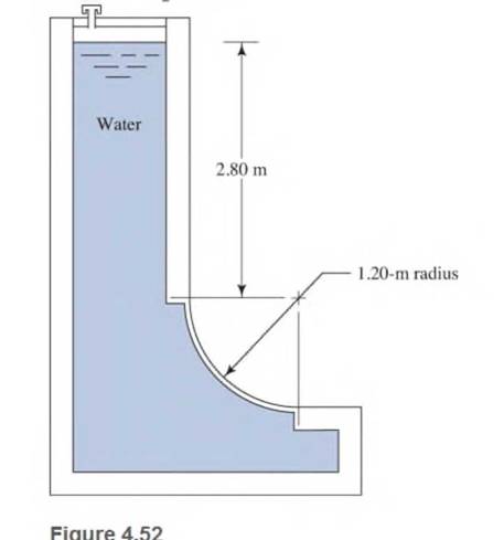
Expert Solution & Answer
Want to see the full answer?
Check out a sample textbook solution
Students have asked these similar questions
using the theorem of three moments, find all the moments, I need concise calculations only
Practise question need help on
Can you show explaination and working. The answer from the text book is Q=5.03 X 10^-3
Chapter 4 Solutions
Applied Fluid Mechanics (7th Edition)
Ch. 4 - figure 4.2 shows a vacuum tank with a flat...Ch. 4 - The flat left end of the tank shown in Fig. 4.21...Ch. 4 - An exhaust system for a room creates a partial...Ch. 4 - A piece of 14 -in Schedule 40 pipe is used as a...Ch. 4 - A pressure relief valve is designed so that the...Ch. 4 - A gas-powered cannon shoots projectiles by...Ch. 4 - The egress hatch of a manned spacecraft is...Ch. 4 - A tank containing liquid ammonia at 77F has a flat...Ch. 4 - The bottom of a laboratory vat has a hole in it to...Ch. 4 - A simple shower for remote locations is designed...
Ch. 4 - Calculate the total force on the bottom of the...Ch. 4 - If the length of the tank in Fig. 4.24 is 1.2m,...Ch. 4 - An observation port in a small submarine is...Ch. 4 - A rectangular gate is installed in a vertical wall...Ch. 4 - '4.15 A vat has a sloped side, as shown in Fig....Ch. 4 - The wall shown in Fig. 4.28 is 20 ft long, (a)...Ch. 4 - If the wall in Fig. 4.29 is 4m long, calculate the...Ch. 4 - Refer to Fig. 4.30Ch. 4 - Refer to Fig. 4.31Ch. 4 - Refer to Fig.4.32Ch. 4 - Refer to Fig 4.33Ch. 4 - Refer to Fig. 4.34Ch. 4 - Refer to Fig. 4.35 (?Ch. 4 - Swimming poo!WilierGlasswindow2 ft diameterFigure...Ch. 4 - 4.25 Refer to Fig 4.37Ch. 4 - Refer to Fig.4.38Ch. 4 - Refer to Fig.4.39Ch. 4 - Refer to Fig.4.40Ch. 4 - Refer to Fig 4.41Ch. 4 - figure 4.42i5 shows a gasoline tank filled into...Ch. 4 - If the tank in Fig. 4.42 is filled just to the...Ch. 4 - If the tank in Fig. 4.42 is only half full of...Ch. 4 - For the water tank shown in Fig. 4.43, compute the...Ch. 4 - For the water tank shown in Fig. 4.43, compute the...Ch. 4 - For the water tank shown in Fig. 4.43, compute the...Ch. 4 - For the orange-drink tank shown in Fig. 4.32,...Ch. 4 - For the orange-drink tank shown in Fig. 4.32,...Ch. 4 - For the oil tank shown in Fig. 4.35, compute the...Ch. 4 - For the oil tank shown in Fig. 4.35; compute the...Ch. 4 - figure 4.44 shows a rectangular gate holding water...Ch. 4 - figure 4.45 shows a gate hinged at its bottom and...Ch. 4 - figure 4.46 shows a tank of water with a circular...Ch. 4 - Repeat Problem 4.19(Fig. 4.31), except that the...Ch. 4 - Repeat Problem 4.22 (Fig. 4.32), except that the...Ch. 4 - Repeat Problem 4.26 (Fig. 4.38 ). except that the...Ch. 4 - Repeat Problem 4.28 (Fig. 4.40 ), except that the...Ch. 4 - Use Fig 4.47. The surface is 2.00m long.Ch. 4 - Use Fig.4.48. The surface is 2.50m long.Ch. 4 - Use Fig.4.49. The surface is 5.00 ft longCh. 4 - Use Fig.4.50. The surface is 4.50 ft long.Ch. 4 - Use Fig.4.51.The surface is 4.00 m long.Ch. 4 - Use Fig .4.52. The surface is 1.50m longCh. 4 - Use Fig. 4.53. The surface is 1.50m long.Ch. 4 - Use Fig. 4.54. The surface is 60 in longCh. 4 - Repeat Problem 4.47 using Fig. 4.47, except that...Ch. 4 - Repeat Problem 4.48 using Fig. 4.48, except that...Ch. 4 - The tank in Fig. 4.55 has a view port in the...Ch. 4 - Insulated concrete forms (ICFs) are becoming more...Ch. 4 - Lacks are installed in rivers to allow boats to...Ch. 4 - When a dam is installed in a river that has...Ch. 4 - A wealthy eccentric is interested in having an...Ch. 4 - A pneumatic cylinder like the one shown in Fig....Ch. 4 - Determine the magnitude and the location of the...Ch. 4 - For the hinged gate shown in Fig. 4.61, determine...Ch. 4 - Prob. 4.65PPCh. 4 - Write a program to solve Problem 4.41 with any...Ch. 4 - Write a program to solve Problem 4.42 (Fig. 4.46)...Ch. 4 - Write a program to solve curved surface problems...Ch. 4 - For Program 1, cause the depth h to vary over some...
Knowledge Booster


Learn more about
Need a deep-dive on the concept behind this application? Look no further. Learn more about this topic, mechanical-engineering and related others by exploring similar questions and additional content below.Similar questions
- practise questionarrow_forwardCan you provide steps and an explaination on how the height value to calculate the Pressure at point B is (-5-3.5) and the solution is 86.4kPa.arrow_forwardPROBLEM 3.46 The solid cylindrical rod BC of length L = 600 mm is attached to the rigid lever AB of length a = 380 mm and to the support at C. When a 500 N force P is applied at A, design specifications require that the displacement of A not exceed 25 mm when a 500 N force P is applied at A For the material indicated determine the required diameter of the rod. Aluminium: Tall = 65 MPa, G = 27 GPa. Aarrow_forward
- Find the equivalent mass of the rocker arm assembly with respect to the x coordinate. k₁ mi m2 k₁arrow_forward2. Figure below shows a U-tube manometer open at both ends and containing a column of liquid mercury of length l and specific weight y. Considering a small displacement x of the manometer meniscus from its equilibrium position (or datum), determine the equivalent spring constant associated with the restoring force. Datum Area, Aarrow_forward1. The consequences of a head-on collision of two automobiles can be studied by considering the impact of the automobile on a barrier, as shown in figure below. Construct a mathematical model (i.e., draw the diagram) by considering the masses of the automobile body, engine, transmission, and suspension and the elasticity of the bumpers, radiator, sheet metal body, driveline, and engine mounts.arrow_forward
- 3.) 15.40 – Collar B moves up at constant velocity vB = 1.5 m/s. Rod AB has length = 1.2 m. The incline is at angle = 25°. Compute an expression for the angular velocity of rod AB, ė and the velocity of end A of the rod (✓✓) as a function of v₂,1,0,0. Then compute numerical answers for ȧ & y_ with 0 = 50°.arrow_forward2.) 15.12 The assembly shown consists of the straight rod ABC which passes through and is welded to the grectangular plate DEFH. The assembly rotates about the axis AC with a constant angular velocity of 9 rad/s. Knowing that the motion when viewed from C is counterclockwise, determine the velocity and acceleration of corner F.arrow_forward500 Q3: The attachment shown in Fig.3 is made of 1040 HR. The static force is 30 kN. Specify the weldment (give the pattern, electrode number, type of weld, length of weld, and leg size). Fig. 3 All dimension in mm 30 kN 100 (10 Marks)arrow_forward
- (read image) (answer given)arrow_forwardA cylinder and a disk are used as pulleys, as shown in the figure. Using the data given in the figure, if a body of mass m = 3 kg is released from rest after falling a height h 1.5 m, find: a) The velocity of the body. b) The angular velocity of the disk. c) The number of revolutions the cylinder has made. T₁ F Rd = 0.2 m md = 2 kg T T₂1 Rc = 0.4 m mc = 5 kg ☐ m = 3 kgarrow_forward(read image) (answer given)arrow_forward
arrow_back_ios
SEE MORE QUESTIONS
arrow_forward_ios
Recommended textbooks for you
 International Edition---engineering Mechanics: St...Mechanical EngineeringISBN:9781305501607Author:Andrew Pytel And Jaan KiusalaasPublisher:CENGAGE L
International Edition---engineering Mechanics: St...
Mechanical Engineering
ISBN:9781305501607
Author:Andrew Pytel And Jaan Kiusalaas
Publisher:CENGAGE L
Physics 33 - Fluid Statics (1 of 10) Pressure in a Fluid; Author: Michel van Biezen;https://www.youtube.com/watch?v=mzjlAla3H1Q;License: Standard YouTube License, CC-BY