
Videos
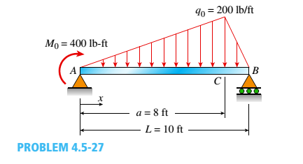
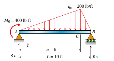
The simple beam ACE shown in the figure is subjected to a triangular load of maximum intensity q0= 200 lb/ft at a = 8 ft and a concentrated moment M = 400 Ib-ft at A.
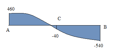
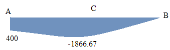
- Draw the shear-force and bending-moment diagrams for this beam,
- Find the value of distanced that results in the maximum moment occurring at L/2. Draw the shear-force and bending-moment diagrams for this case.
- Find the value of distance a for which Mmaxis the largest possible value.
(a).
To draw: Shear force and bending moment diagrams for simply supported beam.
Answer to Problem 4.5.27P
The
Explanation of Solution
Given Information:
Max load
Distance
Moment
Length
Concept Used:
Shear forces and bending moments at various points shall be calculated.
Calculation:
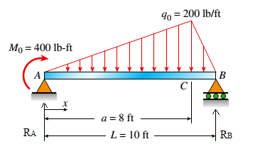
Draw free body diagram
From equilibrium
Also,
From equation
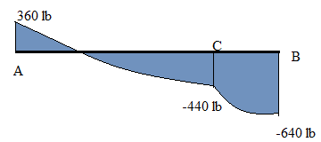
Shear Force calculation
SFD
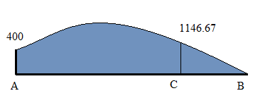
Bending Moment calculation
BMD
Conclusion:
The
(b).
To find: The value of
Answer to Problem 4.5.27P
The distance is
Explanation of Solution
Given Information:
Max load
Distance
Moment
Length
Concept Used:
Shear forces and bending moments at various points shall be calculated.
Calculation:
The free body diagram is as follows:
From equilibrium
Also,
From equation
Bending moment
On solving above equation, we get:
Shear Force calculation:
SFD
Bending Moment calculation:
BMD
Conclusion:
The distance is
(c).
To find: The value of
Answer to Problem 4.5.27P
The distance is
Explanation of Solution
Given Information:
Max load
Distance
Moment
Length
Concept Used:
Bending moment shall be calculated.
Calculation:
The free body diagram:

From part
Bending moment
And maximum bending moment is
Conclusion:
The distance is
Want to see more full solutions like this?
Chapter 4 Solutions
Mechanics of Materials, SI Edition


- The force F={25i−45j+15k}F={25i−45j+15k} lblb acts at the end A of the pipe assembly shown in (Figure 1). Determine the magnitude of the component F1 which acts along the member AB. Determine the magnitude of the component F2 which acts perpendicular to the AB.arrow_forwardHi can you please help me with the attached question?arrow_forwardHi can you please help me with the attached question?arrow_forward
- Please can you help me with the attached question?arrow_forward4. The rod ABCD is made of an aluminum for which E = 70 GPa. For the loading shown, determine the deflection of (a) point B, (b) point D. 1.75 m Area = 800 mm² 100 kN B 1.25 m с Area = 500 mm² 75 kN 1.5 m D 50 kNarrow_forwardResearch and select different values for the R ratio from various engine models, then analyze how these changes affect instantaneous velocity and acceleration, presenting your findings visually using graphs.arrow_forward
 Mechanics of Materials (MindTap Course List)Mechanical EngineeringISBN:9781337093347Author:Barry J. Goodno, James M. GerePublisher:Cengage Learning