
Concept explainers
Videos
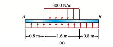
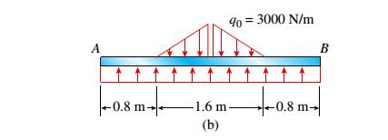
The beam AB shown in the figure supports a uniform load of intensity 3000 N/m acting over half the length of the beam. The beam rests on a foundation that produces a uniformly distributed load over the entire length.
- Draw the shear-force and bending-moment diagrams for this beam.
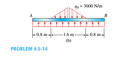
Repeat part (a) for the distributed load variation shown in Fig. b.
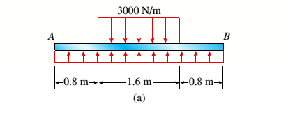
(a)
The shear force and bending moment diagram for the given beam.
Answer to Problem 4.5.14P
Maximum shear force Vmax= y13
Maximum bending moment Mmax=
Explanation of Solution
Given information: The given beam and parameters are shown in the figure below:
For calculating the maximum shear force (V) and bending moment (M) of the given figure, we need to find the amount of force acting upwards on the entire span length.
Shear Force Diagram:
To find the shear force of the given figure, we divide the above figure in a number of sections.
- Firstly taking a section from length 0 to 0.8 m.
- Again taking a section from length 0.8 m to mid-span.
- For the next half of the beam, the shear values can be obtained from the concept of symmetry and the obtained values is shown below in the given shear force diagram.
The value of shear force when x= 0 at point A is
The value of shear force when x= 0.8 at point A is
The value of shear force when x= 0.8 is,
The value of shear force at mid- span when x= 1.6 is,
Bending Moment Diagram:
To find the bending moments of the given figure, we divide the above figure in a number of sections.
- Firstly taking a section from length 0 to 0.8 m.
- Again taking a section from length 0.8 m to mid-span.
- For the next half of the beam, the bending moment values can be obtained from the concept of symmetry and the obtained values is shown below in the given bending moment diagram.
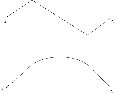
As the equation is of second order of degree, the curve obtained is a parabola.
The value of Moment when x= 0 at point A is
The value of moment when x= 0.8 at point A is
The value of bending moment when x= 0.8 is,
The value of bending moment at mid- span when x= 1.6 is,
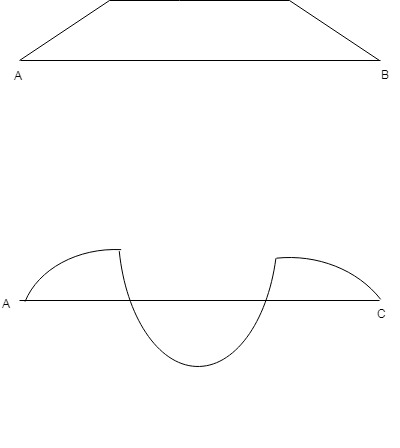
On the basis of above calculation the shear force and bending moment diagram for the given beam is as follows:
(b)
The shear force and bending moment diagram for the given beam.
Answer to Problem 4.5.14P
Maximum shear force Vmax=
Maximum bending moment Mmax=
Explanation of Solution
Given information: The given beam and parameters are shown in the figure below:
For calculating the maximum shear force (V) and bending moment (M) of the given figure, we need to find the amount of force acting upwards on the entire span length.
Shear Force Diagram:
To find the shear force of the given figure we divide the above figure in a number of sections.
- Firstly taking a section from length 0 to 0.8 m.
- Again taking a section from length 0.8 m to mid-span. For obtaining the required shear force value, consider a section X-X for the given uniformly varying load.
- For the next half of the beam, the shear values can be obtained from the concept of symmetry and the obtained values is shown below in the given shear force diagram.
The value of shear force when x= 0 at point A is
The value of shear force when x= 0.8 at point A is
From the triangle similarity,
The value of shear force when x= 0.8 is,
The value of shear force at mid- span when x= 2.4 is,
Bending Moment Diagram:
To find the bending moments of the given figure we divide the above figure in a number of sections.
- Firstly taking a section from length 0 to 0.8 m.
- For obtaining the required shear force value, consider a section X-X for the given uniformly varying load. From the triangle similarity,
- For the next half of the beam, the bending moment values can be obtained from the concept of symmetry and the obtained values is shown below in the given bending moment diagram.
As the equation is of second order of degree, the curve obtained is a parabola.
The value of Moment when x= 0 at point A is
The value of moment when x= 0.8 at point A is
The value of bending moment when x= 0.8 is,
The value of bending moment at mid- span when x= 1.6 is,
On the basis of above calculation the shear force and bending moment diagram for the given beam is as follows:
Want to see more full solutions like this?
Chapter 4 Solutions
Bundle: Mechanics Of Materials, Loose-leaf Version, 9th + Mindtap Engineering, 1 Term (6 Months) Printed Access Card


- Weight of Air: If you could collect the air in a square inch column of air starting at sea level going all the way to space, how much would it weigh? Answer with one decimal. Do not write the unit.arrow_forwardPiston Area: (Q2) A cylinder applies a force of 400 pounds in extension. If the pressure in the cylinder is 39 psi what is the area of the piston in square inches? Use πon your calculator Answer with two decimals. Do not write the unit.arrow_forwardA 2D incompressible flow has velocitycomponents u= X^2 - 2y^2 and v=aX^b y^c ,where a, b, and c are numbers. Find the values of a, b, and c Find the stream functionarrow_forward
- Please can you assist with the attached question please?arrow_forward(a) Find a second-order homogeneous linear ODE for which the given functions are solutions. (b) Show linear independence by the Wronskian. (c) Solve the initial value problem. a. cos(5x), sin(5x), y(0) = 3, y'(0) = −5 b. e-2.5x cos(0.3x), e-2.5x sin(0.3x), y(0) = 3, y'(0) = -7.5arrow_forwardSolve the IVP. a. y" 16y 17e* ; = y(0) = 6, y'(0) = -2 b. (D² + 41)y = sin(t) + ½ sin(3t) + sin(t) ; y(0) = 0, y'(0) : = 35 31arrow_forward
- Find the general solution. a. y' 5y = 3ex - 2x + 1 - b. y" +4y' + 4y = e¯*cos(x) c. (D² + I)y = cos(wt), w² # 1arrow_forwardhandwritten solutions, please!!arrow_forward> Homework 4 - Spring 2025.pdf Spring 2025.pdf k 4 - Spring 2025.pdf (447 KB) Due: Thursday, February 27 Page 1 > of 2 ZOOM 1. A simply supported shaft is shown in Figure 1 with wo = 25 N/cm and M = 20 N cm. Use singularity functions to determine the reactions at the supports. Assume EI = 1000 kN cm². M Wo 0 10 20 30 40 50 60 70 80 90 100 110 cm Figure 1 - Problem 1 2. A support hook was formed from a rectangular bar. Find the stresses at the inner and outer surfaces at sections just above and just below O-B. 210 mmarrow_forward
- A distillation column with a total condenser and a partial reboiler is separating ethanol andwater at 1.0 atm. Feed is 0.32 mol fraction ethanol and it enters as a saturated liquid at 100mol/s on the optimum plate. The distillate product is a saturated liquid with 80 mol% ethanol.The condenser removes 5615 kW. The bottoms product is 0.05 mol fraction ethanol. AssumeCMO is valid.(a) Find the number of equilibrium stages for this separation. [6 + PR](b) Find how much larger the actual reflux ratio, R, used is than Rmin, i.e. R/Rmin. [3]Note: the heats of vaporization of ethanol and water are λe = 38.58 and λw = 40.645 arrow_forwardWe have a feed that is a binary mixture of methanol and water (60.0 mol% methanol) that issent to a system of two flash drums hooked together. The vapor from the first drum is cooled,which partially condenses the vapor, and then is fed to the second flash drum. Both drumsoperate at 1.0 atm and are adiabatic. The feed to the first drum is 1000 kmol/hr. We desire aliquid product from the first drum that is 35.0 mol% methanol. The second drum operates at afraction vaporized of (V/F)2 = 0.25.(a) Find the liquid flow rate leaving the first flash drum, L1 (kmol/hr). [286 kmol/hr](b) Find the vapor composition leaving the second flash drum, y2. [0.85]arrow_forward= The steel curved bar shown has rectangular cross-section with a radial height h = 6 mm and thickness b = 4mm. The radius of the centroidal axis is R = 80 mm. A force P = 10 N is applied as shown. Assume the steel modulus of 207,000 MPa and G = 79.3(103) MPa, repectively. elasticity and shear modulus E = Find the vertical deflection at point B. Use Castigliano's method for a curved flexural member and since R/h > 10, neglect the effect of shear and axial load, thereby assuming that deflection is due to merely the bending moment. Note the inner and outer radii of the curves bar are: r = 80 + ½ (6) = 83 mm, r₁ = 80 − ½ (6) = 77 mm 2 2 Sπ/2 sin² 0 d = √π/² cos² 0 d0 = Π 0 4 大 C R B Parrow_forward
 Mechanics of Materials (MindTap Course List)Mechanical EngineeringISBN:9781337093347Author:Barry J. Goodno, James M. GerePublisher:Cengage Learning