
Mastering Engineering with Pearson eText -- Standalone Access Card -- for Electrical Engineering: Principles & Applications
7th Edition
ISBN: 9780134486970
Author: Allan R. Hambley
Publisher: PEARSON
expand_more
expand_more
format_list_bulleted
Concept explainers
Videos
Textbook Question
Chapter 4, Problem 4.40P
Consider the circuit shown in Figure P4.40. A voltmeter (VM) is connected across the inductance. The switch has been closed for a long time. When the switch is opened, an arc appears across the switch contacts. Explain why. Assuming an ideal switch and inductor, what voltage appears across the inductor when the switch is opened? What could happen to the voltmeter when the switch opens?
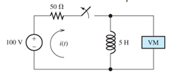
Figure P4.40
Expert Solution & Answer
Want to see the full answer?
Check out a sample textbook solution
Students have asked these similar questions
I need help in creating a matlab code to find the currents USING MARTIXS AND INVERSE to find the current
Problem 3
(a) Consider
x[n]
=
{
0,
1, 0 ≤ n ≤N-1
otherwise
_and_h[n] = {
1, 0 ≤ n ≤M-1
0, otherwise
with N > M. Plot the sequence y[n] = x[n] × h[n]. Make sure to specify the amplitude values
*
and time indices n of y[n] where y[n] is constant.
(b) Express the number L of samples of y[n] that are non-zero in terms of M and N.
(c) Consider
x'[n]
=
{
0,
1, N₁ ≤ n ≤ N₂
otherwise
1, M₁n M₂
and h'[n] =
=
0, otherwise
',
and assume that №2 - N₁ = N-1 and M2 - M₁
=
x'[n] h'[n] is equal to a shifted version of y[n]. What is the value of the shift?
-
= M 1. Show that the sequence y'[n]
=
Home Work
Calculate I, and I2 in the two-port of Fig. below
20
211=602
2/30° V
V₁
%12=-142
721=-j4 2
Z22=82
+
V₂
94
Chapter 4 Solutions
Mastering Engineering with Pearson eText -- Standalone Access Card -- for Electrical Engineering: Principles & Applications
Ch. 4 - Suppose we have a capacitance C discharging...Ch. 4 - The dielectric materials used in real capacitors...Ch. 4 - The initial voltage across the capacitor shown in...Ch. 4 - A 100F capacitance is initially charged to 1000 V....Ch. 4 - At t = 0, a charged 10{ F capacitance is connected...Ch. 4 - At time t1 , a capacitance C is charged to a...Ch. 4 - Given an initially charged capacitance that begins...Ch. 4 - The initial voltage across the capacitor shown in...Ch. 4 - In physics, the half-life is often used to...Ch. 4 - We know that a 50F capacitance is charged to an...
Ch. 4 - We know that the capacitor shown in Figure P4.11...Ch. 4 - The purchasing power P of a certain unit of...Ch. 4 - Derive an expression for vC(t) in the circuit of...Ch. 4 - Suppose that at t= 0, we connect an uncharged 10 F...Ch. 4 - Suppose we have a capacitance C that is charged to...Ch. 4 - A person shuffling across a dry carpet can be...Ch. 4 - Prob. 4.17PCh. 4 - Consider the circuit shown in Figure P4.18. Prior...Ch. 4 - List the steps for dc steady-state analysis of RLC...Ch. 4 - Explain why we replace capacitances with open...Ch. 4 - Solve for the steady-state values of i1, i2, and...Ch. 4 - Consider the circuit shown in Figure P4.22. What...Ch. 4 - In the circuit of Figure P4.23, the switch is in...Ch. 4 - The circuit shown in Figure P4.24 has been set up...Ch. 4 - Solve for the steady-state values of i1 , i2, i3,...Ch. 4 - The circuit shown in Figure P4.26 is operating in...Ch. 4 - Prob. 4.27PCh. 4 - Consider the circuit of Figure P4.28 in which the...Ch. 4 - For the circuit shown in Figure P4.29, the switch...Ch. 4 - Consider the circuit of Figure P4.30 in which the...Ch. 4 - Give the expression for the time constant of a...Ch. 4 - A circuit consists of switches that open or close...Ch. 4 - The circuit shown in Figure P4.33 is operating in...Ch. 4 - Consider the circuit shown in Figure P4.34. The...Ch. 4 - Repeat Problem P4.34 given iL(0)=0A .Ch. 4 - Real inductors have series resistance associated...Ch. 4 - Determine expressions for and sketch is(t) to...Ch. 4 - For the circuit shown in Figure P4.38,, find an...Ch. 4 - The circuit shown in Figure P4.39 is operating in...Ch. 4 - Consider the circuit shown in Figure P4.40. A...Ch. 4 - Due to components not shown in the figure, the...Ch. 4 - The switch shown in Figure P4.42 has been closed...Ch. 4 - Determine expressions for and sketch vR(t) to...Ch. 4 - What are the steps in solving a circuit having a...Ch. 4 - Prob. 4.45PCh. 4 - Solve for vC(t) for t > 0 in the circuit of Figure...Ch. 4 - Solve for v(t) for t > 0 in the circuit of Figure...Ch. 4 - Prob. 4.48PCh. 4 - Consider the circuit shown inFigure P4.49. The...Ch. 4 - Consider the circuit shown in Figure P4.50. The...Ch. 4 - The voltage source shown in Figure P4.51 is called...Ch. 4 - Determine the form of the particular solution for...Ch. 4 - Determine the form of the particular solution for...Ch. 4 - Prob. 4.54PCh. 4 - Prob. 4.55PCh. 4 - How can first-or second-order circuits be...Ch. 4 - Prob. 4.57PCh. 4 - Prob. 4.58PCh. 4 - Prob. 4.59PCh. 4 - Sketch a step response for a second-order system...Ch. 4 - A dc source is connected to a series RLC circuit...Ch. 4 - Repeat Problem P4.61 for R = 40 .Ch. 4 - Repeat Problem P4.61 for R = 20 .Ch. 4 - Prob. 4.64PCh. 4 - Repeat Problem P4.64 for R=50 .Ch. 4 - Repeat Problem P4.64 for R=500 .Ch. 4 - Solve for i(t) for t > 0 in the circuit of Figure...Ch. 4 - Prob. 4.68PCh. 4 - Prob. 4.69PCh. 4 - Prob. 4.70PCh. 4 - Use MATLAB to derive an expression for vc(t)in the...Ch. 4 - Prob. 4.72PCh. 4 - Consider the circuit shown in FigureP4.50 in which...Ch. 4 - Prob. 4.74PCh. 4 - Prob. 4.75PCh. 4 - Use MATLAB to solve for the mesh currents in the...Ch. 4 - The switch m the circuit shown in Figure T4.1 is...Ch. 4 - Prob. 4.2PTCh. 4 - Consider the circuit shown in Figure T4.3. Figure...Ch. 4 - Consider the circuit shown in Figure T4.4 in which...Ch. 4 - Write the MATLAB commands to obtain the solution...
Knowledge Booster


Learn more about
Need a deep-dive on the concept behind this application? Look no further. Learn more about this topic, electrical-engineering and related others by exploring similar questions and additional content below.Similar questions
- HW-2: Consider the loop of Figure below. If B = 0.5az Wb/m2, R = 20 2, e = 10 cm, and the rod is moving with a constant velocity of 8ax m/s, find (a) The induced emf in the rod (b) The current through the resistor y I 00 121 & B (in) 60 Answer: (a) 0.4 V, (b) 20 mA &arrow_forwardWrite a Verilog program to design the 4-bit ripple carry counter using the instantiation process available in Verilog HDL and write the stimulus program to check the functionality of the design. Assume 4-bit ripple carry counter is designed from a T-flipflop and T-flipflop is designed from a D- flipflop.arrow_forwardHW3: A 9.375-GHz uniform plane wave is propagating in polyethylene (&-2.26). If the amplitude of the electric field intensity is 500 V/m and the material is assumed to be lossless, find: (a) the phase constant; (b) thearrow_forward
- HW1: The location of the sliding bar in Figure below is given by x = 5t + 2t³, and the separation of the two rails is 20 cm. Let B = 0.8x2a, T. Find the voltmeter reading at (a) t = 0.4 s; (b) x = 0.6 m.arrow_forwardFor the circuit shown in Fig. 2.18, he =1.1 K2, hfe =50. Find Avf, Rif and Rof. { Ans: -3.2; 1935; X2807. Ans:-3-2;193;728. Vcc Rs=10kQ RF = 40kQ Re=4KQ -ov Vsarrow_forwardFor the system shown in figure below, the per unit values of different quantities are E-1.2, V 1, X X2-0.4. Xa-0.2 Determine whether the system is stable for a sustained fault. The fault is cleared at 8-60°. Is the system stable? If so find the maximum rotor swing. Find the critical clearing angle. E25 G X'd 08 CB X2 F CB V28 Infinite busarrow_forward
- 17 For the circuit shown in Fig. 2.20, the transistors are identical and have the following parameters: hfe = 50, hie 1.1K, hre = 0, and hoe = 0. Calculate Auf, Rif and Rof. 25 V {Ans #45.4; 112 KM; 129 150k 47k www www +11 www 10k 6 4.7k 50μF Rif R₂1000 w 4.7k 47k Vo Q2 33k 4.7k ww 50µF 5μF 4.7k 1 R₁ Rofarrow_forwardFor the circuit shown in Fig. 2.18, he =1.1 K2, hfe =50. Find Avf, Rif and Rof. { Ans: -3.2; 1935; X2807. Ans:-3-2;193;728. Vcc Rs=10kQ RF = 40kQ Re=4KQ -ov Vs Fig. 2.18 Circuit for Q5.arrow_forwardThe circuit of Fig. 2.16 is to have Af=-1mA/V, D=1+ BA = 50, a voltage gain of -4, Rs =1KQ, and hfe = 150. Find RL, Re, Rif and Rof.. Vcc www RL OV Ans: 4 kor; 98053150 KS;∞. { An Re Fig. 2.16 Circuit for Q3.arrow_forward
- During the lab you will design and measure a differential amplifier, made with an opamp. inside generator R5 ww 500 V1 0.1Vpk 1kHz 0° R6 w 50Ω R1 ww 10ΚΩ VCC C1 balanced wire R3 w 15.0V signal+ 100nF U1A TL082CP ground 2 signal- R4 w C2 Question5: Calculate R3 and R4 for a 20dB. 100nF VEE -15.0V R2 ww 10ΚΩarrow_forwardnot use ai pleasearrow_forward3. Consider the system described by the transfer function Gp(s) polynomial controller to satisfy the below specifications: 1) The settling time is t = 1 second, 2) 0.1% peak overshoot, 3) and zero steady-state error for a ramp input. The sampling period is T = 0.01 second. 1 = Design a discrete-time s(s+5)*arrow_forward
arrow_back_ios
SEE MORE QUESTIONS
arrow_forward_ios
Recommended textbooks for you
 Electricity for Refrigeration, Heating, and Air C...Mechanical EngineeringISBN:9781337399128Author:Russell E. SmithPublisher:Cengage Learning
Electricity for Refrigeration, Heating, and Air C...
Mechanical Engineering
ISBN:9781337399128
Author:Russell E. Smith
Publisher:Cengage Learning
Electrical Measuring Instruments - Testing Equipment Electrical - Types of Electrical Meters; Author: Learning Engineering;https://www.youtube.com/watch?v=gkeJzRrwe5k;License: Standard YouTube License, CC-BY
01 - Instantaneous Power in AC Circuit Analysis (Electrical Engineering); Author: Math and Science;https://www.youtube.com/watch?v=If25y4Nhvw4;License: Standard YouTube License, CC-BY