
Mastering Engineering with Pearson eText -- Standalone Access Card -- for Electrical Engineering: Principles & Applications
7th Edition
ISBN: 9780134486970
Author: Allan R. Hambley
Publisher: PEARSON
expand_more
expand_more
format_list_bulleted
Videos
Textbook Question
Chapter 4, Problem 4.22P
Consider the circuit shown in Figure P4.22. What is the steady-state value of
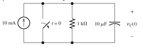
Figure P4.22
Expert Solution & Answer

Learn your wayIncludes step-by-step video

schedule05:37
Students have asked these similar questions
R1 is 978 ohms R2 is 2150 ohms R3 is 4780
R1 is parallel to R2 and R2 is parallel to R3 and R1 and R3 are in series
Q7 For the circuit shown in Fig. 2.20, the transistors are identical and have the following
parameters: hfe = 50, hie = 1.1K, hre = 0, and hoe = 0. Calculate Auf, Rif and Rof.
Ans: 45.4; 112 KQ; 129.
25 V
10k
47k
4.7k
Vo
150k
w
Vs
47k
4.7k
W
22
5μF
33k
50uF
50μF
4.7k
4.7k
R₁
Rof
Rif
R1000
Fig. 2.20 Circuit for Q7.
Q6)) The transistors in the feedback amplifier shown are
identical, and their h-parameters are..
hie = 1.1k, hfe = 50, hre=o, and hoe = 0. Calculate Auf, Rif and
Rof. {Ans: 6031583; 4. Kor.
Is 4
4.7 k
www
4.7k
91k 4.7k
91k
10k
1k.
10k
21000
4.7k
w
15k
Fig. 2.19 Circuit for Q6.
Chapter 4 Solutions
Mastering Engineering with Pearson eText -- Standalone Access Card -- for Electrical Engineering: Principles & Applications
Ch. 4 - Suppose we have a capacitance C discharging...Ch. 4 - The dielectric materials used in real capacitors...Ch. 4 - The initial voltage across the capacitor shown in...Ch. 4 - A 100F capacitance is initially charged to 1000 V....Ch. 4 - At t = 0, a charged 10{ F capacitance is connected...Ch. 4 - At time t1 , a capacitance C is charged to a...Ch. 4 - Given an initially charged capacitance that begins...Ch. 4 - The initial voltage across the capacitor shown in...Ch. 4 - In physics, the half-life is often used to...Ch. 4 - We know that a 50F capacitance is charged to an...
Ch. 4 - We know that the capacitor shown in Figure P4.11...Ch. 4 - The purchasing power P of a certain unit of...Ch. 4 - Derive an expression for vC(t) in the circuit of...Ch. 4 - Suppose that at t= 0, we connect an uncharged 10 F...Ch. 4 - Suppose we have a capacitance C that is charged to...Ch. 4 - A person shuffling across a dry carpet can be...Ch. 4 - Prob. 4.17PCh. 4 - Consider the circuit shown in Figure P4.18. Prior...Ch. 4 - List the steps for dc steady-state analysis of RLC...Ch. 4 - Explain why we replace capacitances with open...Ch. 4 - Solve for the steady-state values of i1, i2, and...Ch. 4 - Consider the circuit shown in Figure P4.22. What...Ch. 4 - In the circuit of Figure P4.23, the switch is in...Ch. 4 - The circuit shown in Figure P4.24 has been set up...Ch. 4 - Solve for the steady-state values of i1 , i2, i3,...Ch. 4 - The circuit shown in Figure P4.26 is operating in...Ch. 4 - Prob. 4.27PCh. 4 - Consider the circuit of Figure P4.28 in which the...Ch. 4 - For the circuit shown in Figure P4.29, the switch...Ch. 4 - Consider the circuit of Figure P4.30 in which the...Ch. 4 - Give the expression for the time constant of a...Ch. 4 - A circuit consists of switches that open or close...Ch. 4 - The circuit shown in Figure P4.33 is operating in...Ch. 4 - Consider the circuit shown in Figure P4.34. The...Ch. 4 - Repeat Problem P4.34 given iL(0)=0A .Ch. 4 - Real inductors have series resistance associated...Ch. 4 - Determine expressions for and sketch is(t) to...Ch. 4 - For the circuit shown in Figure P4.38,, find an...Ch. 4 - The circuit shown in Figure P4.39 is operating in...Ch. 4 - Consider the circuit shown in Figure P4.40. A...Ch. 4 - Due to components not shown in the figure, the...Ch. 4 - The switch shown in Figure P4.42 has been closed...Ch. 4 - Determine expressions for and sketch vR(t) to...Ch. 4 - What are the steps in solving a circuit having a...Ch. 4 - Prob. 4.45PCh. 4 - Solve for vC(t) for t > 0 in the circuit of Figure...Ch. 4 - Solve for v(t) for t > 0 in the circuit of Figure...Ch. 4 - Prob. 4.48PCh. 4 - Consider the circuit shown inFigure P4.49. The...Ch. 4 - Consider the circuit shown in Figure P4.50. The...Ch. 4 - The voltage source shown in Figure P4.51 is called...Ch. 4 - Determine the form of the particular solution for...Ch. 4 - Determine the form of the particular solution for...Ch. 4 - Prob. 4.54PCh. 4 - Prob. 4.55PCh. 4 - How can first-or second-order circuits be...Ch. 4 - Prob. 4.57PCh. 4 - Prob. 4.58PCh. 4 - Prob. 4.59PCh. 4 - Sketch a step response for a second-order system...Ch. 4 - A dc source is connected to a series RLC circuit...Ch. 4 - Repeat Problem P4.61 for R = 40 .Ch. 4 - Repeat Problem P4.61 for R = 20 .Ch. 4 - Prob. 4.64PCh. 4 - Repeat Problem P4.64 for R=50 .Ch. 4 - Repeat Problem P4.64 for R=500 .Ch. 4 - Solve for i(t) for t > 0 in the circuit of Figure...Ch. 4 - Prob. 4.68PCh. 4 - Prob. 4.69PCh. 4 - Prob. 4.70PCh. 4 - Use MATLAB to derive an expression for vc(t)in the...Ch. 4 - Prob. 4.72PCh. 4 - Consider the circuit shown in FigureP4.50 in which...Ch. 4 - Prob. 4.74PCh. 4 - Prob. 4.75PCh. 4 - Use MATLAB to solve for the mesh currents in the...Ch. 4 - The switch m the circuit shown in Figure T4.1 is...Ch. 4 - Prob. 4.2PTCh. 4 - Consider the circuit shown in Figure T4.3. Figure...Ch. 4 - Consider the circuit shown in Figure T4.4 in which...Ch. 4 - Write the MATLAB commands to obtain the solution...
Knowledge Booster


Learn more about
Need a deep-dive on the concept behind this application? Look no further. Learn more about this topic, electrical-engineering and related others by exploring similar questions and additional content below.Similar questions
- Q5 For the circuit shown in Fig. 2.18, hie =1.1 KQ, hfe =50. Find Avf, Rif and Rof Ans: -3.2; 193 ; 728 N. Vcc Vs Rs=10kQ Re=4KQ RF - = 40ΚΩ www Fig. 2.18 Circuit for Qs.arrow_forwardSheet No.2 Qi For the source follower shown in Fig. 2.14, Ipss =16 mA, V₂ =-4V, and VGsQ=-2.86 V. Find Avf, Rif and Rof. Assume rd is high. Ans: 0.833; ∞0; 365.7 . VDD Vo Vs R = 2.2 k Fig. 2.14 Circuit for Qi.arrow_forwardQ4 For the circuit shown in Fig. 2.17, he-100, he -1KQ. Find A, A, R and Rof- Ans:-100; -5; 100 K; 250K. Voc RB = 100 k R.=5k Vs Rs 500 R. = 1 kn Fig. 2.17 Circuit for Quarrow_forward
- Q3 The circuit of Fig. 2.16 is to have Af = -1 mA/V, D=1+ BA=50, a voltage gain of -4, Rs = 1KQ, and hfe = 150. Find RL, Re, Rif and Rof. Ans: 4 KN; 980 ; 150 KN; ∞. Vcc RL Vs -OV +11 Fig. 2.16 Circuit for Q3.arrow_forwardQ2 For the circuit shown in Fig. 2.15 hfe =150, hie =1KQ. Find Avf and Rif. Ans: 0.986; 152 KN. Vee R=4k2 Rs 1kQ Vo V, VR=1 KQ Fig. 2.15 Circuit for Q2-arrow_forwardR1 is 978 ohms, R2 is 2150 ohms R3 is 4780 ohmsarrow_forward
- Pleasw draw the block diagram, don't type out what it could look like. Draw it. Thank youarrow_forward(Keynes model in continuous time) A continuous version of the Keynes modelis given by the equationsY= C + I + GT*(dC/dt) + C = aYT*(dI/dt) + I = b*(dC/dt)Write the equations in state space form, and give the conditions for stability.arrow_forwardCan the expert solve an Integral In detall? ⑥M-1 大 80*10万 1012 es dw 7010 80x10³ ⒸP= 1 Sin (Iwl+1) dw 70x10xarrow_forward
- Q1:A) Draw the directional control of DC motor using a relay. Switch controlled by PLC +V Ov (a) Motor OV (b) Motor 10 B) Define the encoder with mention its types. The term encoder is used for a device that provides a digital output as a result of angular or linear displacement. incremental encoder 2 6 absolute encoder 2 10 Q2: A) Suppose that PLC connected to three pushbutton switches as shown in this illustration: 4 2000000 0000 000000 0000 Draw a Ladder Diagram program for PLC to turn the lamp ON when the switch statuses be: Switch A = pressed, Switch B = pressed, Switch C = pressed 1:0 I:0 I:0 0:0 H/HH/H 2 Managemenarrow_forwardExample2:- 8. = e.A nia +2.1 = Find the maximum steady-state power capability of a system consisting of a generator equivalent reactance of 0.4pu connected to an infinite bus through a series reactance of 1.0 p.u. The terminal voltage of the generator is held at1.10 p.u. and the voltage of the infinite bus is 1.0 p.u.arrow_forwardB) A 60-Hz generator is supplying 60% of P max to an infinite bus through a reactive network. A fault occurs which increases the reactance of the network between the generator internal voltage and the infinite bus by 400%. When the fault is cleared, the maximum power that can be delivered is 80% of the original maximum value. Determine the critical clearing angle for the condition described.arrow_forward
arrow_back_ios
SEE MORE QUESTIONS
arrow_forward_ios
Recommended textbooks for you
 Introductory Circuit Analysis (13th Edition)Electrical EngineeringISBN:9780133923605Author:Robert L. BoylestadPublisher:PEARSON
 Delmar's Standard Textbook Of ElectricityElectrical EngineeringISBN:9781337900348Author:Stephen L. HermanPublisher:Cengage Learning
 Programmable Logic ControllersElectrical EngineeringISBN:9780073373843Author:Frank D. PetruzellaPublisher:McGraw-Hill Education
 Fundamentals of Electric CircuitsElectrical EngineeringISBN:9780078028229Author:Charles K Alexander, Matthew SadikuPublisher:McGraw-Hill Education
 Electric Circuits. (11th Edition)Electrical EngineeringISBN:9780134746968Author:James W. Nilsson, Susan RiedelPublisher:PEARSON
 Engineering ElectromagneticsElectrical EngineeringISBN:9780078028151Author:Hayt, William H. (william Hart), Jr, BUCK, John A.Publisher:Mcgraw-hill Education,
Introductory Circuit Analysis (13th Edition)
Electrical Engineering
ISBN:9780133923605
Author:Robert L. Boylestad
Publisher:PEARSON
Delmar's Standard Textbook Of Electricity
Electrical Engineering
ISBN:9781337900348
Author:Stephen L. Herman
Publisher:Cengage Learning
Programmable Logic Controllers
Electrical Engineering
ISBN:9780073373843
Author:Frank D. Petruzella
Publisher:McGraw-Hill Education
Fundamentals of Electric Circuits
Electrical Engineering
ISBN:9780078028229
Author:Charles K Alexander, Matthew Sadiku
Publisher:McGraw-Hill Education
Electric Circuits. (11th Edition)
Electrical Engineering
ISBN:9780134746968
Author:James W. Nilsson, Susan Riedel
Publisher:PEARSON
Engineering Electromagnetics
Electrical Engineering
ISBN:9780078028151
Author:Hayt, William H. (william Hart), Jr, BUCK, John A.
Publisher:Mcgraw-hill Education,
ECE320 Lecture1-3c: Steady-State Error, System Type; Author: Rose-Hulman Online;https://www.youtube.com/watch?v=hG7dq-51AAg;License: Standard Youtube License