
Mastering Engineering with Pearson eText -- Standalone Access Card -- for Electrical Engineering: Principles & Applications
7th Edition
ISBN: 9780134486970
Author: Allan R. Hambley
Publisher: PEARSON
expand_more
expand_more
format_list_bulleted
Videos
Textbook Question
Chapter 4, Problem 4.25P
Solve for the steady-state values of
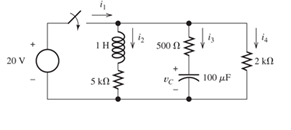
Figure P4.25
Expert Solution & Answer
Want to see the full answer?
Check out a sample textbook solution
Students have asked these similar questions
1. Consider a negative unity-feedback control system whose plant transfer function is type-
1. Suppose you want to build a lead compensator so that -3 ± 5j are dominant poles.
You observed that the angle deficiency at the desired dominant pole is 50°. Compute a
's+b'
and b of the lead compensator (s+ 2) so that the error constant Ky is maximized. In other
words, design the lead compensator in a way so that the steady-state error for ramp input
is minimum
EXAMPLE 8.12 The E-MOSFET of Fig. 8.40 was analyzed in Example 7.10, with the
result that k = 0.24 × 10³ A/V², VGS = 6.4 V, and ID = 2.75 mA.
a. Determine gm-
b. Find rd.
c. Calculate Z; with and without rd. Compare results.
d. Find Zo with and without ra. Compare results.
e. Find A, with and without rd. Compare results.
카
1 uF
Z
RE
912 V
Rp
• 2 ΚΩ
10 ΜΩ
HE
1 μF
ID (on) = 6 mA
VGS (on) = 8 V
VGS (Th) = 3 V
80s = 20 μs
Za
o Vo
NO AI PLEASE
Chapter 4 Solutions
Mastering Engineering with Pearson eText -- Standalone Access Card -- for Electrical Engineering: Principles & Applications
Ch. 4 - Suppose we have a capacitance C discharging...Ch. 4 - The dielectric materials used in real capacitors...Ch. 4 - The initial voltage across the capacitor shown in...Ch. 4 - A 100F capacitance is initially charged to 1000 V....Ch. 4 - At t = 0, a charged 10{ F capacitance is connected...Ch. 4 - At time t1 , a capacitance C is charged to a...Ch. 4 - Given an initially charged capacitance that begins...Ch. 4 - The initial voltage across the capacitor shown in...Ch. 4 - In physics, the half-life is often used to...Ch. 4 - We know that a 50F capacitance is charged to an...
Ch. 4 - We know that the capacitor shown in Figure P4.11...Ch. 4 - The purchasing power P of a certain unit of...Ch. 4 - Derive an expression for vC(t) in the circuit of...Ch. 4 - Suppose that at t= 0, we connect an uncharged 10 F...Ch. 4 - Suppose we have a capacitance C that is charged to...Ch. 4 - A person shuffling across a dry carpet can be...Ch. 4 - Prob. 4.17PCh. 4 - Consider the circuit shown in Figure P4.18. Prior...Ch. 4 - List the steps for dc steady-state analysis of RLC...Ch. 4 - Explain why we replace capacitances with open...Ch. 4 - Solve for the steady-state values of i1, i2, and...Ch. 4 - Consider the circuit shown in Figure P4.22. What...Ch. 4 - In the circuit of Figure P4.23, the switch is in...Ch. 4 - The circuit shown in Figure P4.24 has been set up...Ch. 4 - Solve for the steady-state values of i1 , i2, i3,...Ch. 4 - The circuit shown in Figure P4.26 is operating in...Ch. 4 - Prob. 4.27PCh. 4 - Consider the circuit of Figure P4.28 in which the...Ch. 4 - For the circuit shown in Figure P4.29, the switch...Ch. 4 - Consider the circuit of Figure P4.30 in which the...Ch. 4 - Give the expression for the time constant of a...Ch. 4 - A circuit consists of switches that open or close...Ch. 4 - The circuit shown in Figure P4.33 is operating in...Ch. 4 - Consider the circuit shown in Figure P4.34. The...Ch. 4 - Repeat Problem P4.34 given iL(0)=0A .Ch. 4 - Real inductors have series resistance associated...Ch. 4 - Determine expressions for and sketch is(t) to...Ch. 4 - For the circuit shown in Figure P4.38,, find an...Ch. 4 - The circuit shown in Figure P4.39 is operating in...Ch. 4 - Consider the circuit shown in Figure P4.40. A...Ch. 4 - Due to components not shown in the figure, the...Ch. 4 - The switch shown in Figure P4.42 has been closed...Ch. 4 - Determine expressions for and sketch vR(t) to...Ch. 4 - What are the steps in solving a circuit having a...Ch. 4 - Prob. 4.45PCh. 4 - Solve for vC(t) for t > 0 in the circuit of Figure...Ch. 4 - Solve for v(t) for t > 0 in the circuit of Figure...Ch. 4 - Prob. 4.48PCh. 4 - Consider the circuit shown inFigure P4.49. The...Ch. 4 - Consider the circuit shown in Figure P4.50. The...Ch. 4 - The voltage source shown in Figure P4.51 is called...Ch. 4 - Determine the form of the particular solution for...Ch. 4 - Determine the form of the particular solution for...Ch. 4 - Prob. 4.54PCh. 4 - Prob. 4.55PCh. 4 - How can first-or second-order circuits be...Ch. 4 - Prob. 4.57PCh. 4 - Prob. 4.58PCh. 4 - Prob. 4.59PCh. 4 - Sketch a step response for a second-order system...Ch. 4 - A dc source is connected to a series RLC circuit...Ch. 4 - Repeat Problem P4.61 for R = 40 .Ch. 4 - Repeat Problem P4.61 for R = 20 .Ch. 4 - Prob. 4.64PCh. 4 - Repeat Problem P4.64 for R=50 .Ch. 4 - Repeat Problem P4.64 for R=500 .Ch. 4 - Solve for i(t) for t > 0 in the circuit of Figure...Ch. 4 - Prob. 4.68PCh. 4 - Prob. 4.69PCh. 4 - Prob. 4.70PCh. 4 - Use MATLAB to derive an expression for vc(t)in the...Ch. 4 - Prob. 4.72PCh. 4 - Consider the circuit shown in FigureP4.50 in which...Ch. 4 - Prob. 4.74PCh. 4 - Prob. 4.75PCh. 4 - Use MATLAB to solve for the mesh currents in the...Ch. 4 - The switch m the circuit shown in Figure T4.1 is...Ch. 4 - Prob. 4.2PTCh. 4 - Consider the circuit shown in Figure T4.3. Figure...Ch. 4 - Consider the circuit shown in Figure T4.4 in which...Ch. 4 - Write the MATLAB commands to obtain the solution...
Knowledge Booster


Learn more about
Need a deep-dive on the concept behind this application? Look no further. Learn more about this topic, electrical-engineering and related others by exploring similar questions and additional content below.Similar questions
- NO AI PLEASEarrow_forwardI need handwritten solution to this, electrical engineering expert tutor s only,this is an assignment,I need 100% accuracyarrow_forward5. Determine the CT convolutions for the signals below. Sketch the signal that flips and on same plot the one that is not flipped. Do this for each overlap case. Clearly indicate all overlap cases and the integral limits. Finally, using the left squiggly bracket notation, show the output for each case versus time. (c) 4 x(t) 2 1 2(t) 4 x(t) 4 0123 et 20 x(t) (4) 4 (a) +(1) 24 T 0123 (b) T (f) 1 2-2 0123 (c) (f) 0123 (d) (1) A t 1(8) 4,121 -101 3 (e)arrow_forward
- Solve by pen and paper not using chatgpt or AI Find the current io, and the voltage vo in the circuit in Figure 4. Answer: ἱο = 1.799 Α, νο = 17.99 V.arrow_forward"Hi Tutor, Please solve this question manually without using AI tools. AI solutions are often inaccurate in advanced electrical engineering. If you're unable to solve it manually, kindly let another qualified tutor assist me. I need reliable and accurate solutions. Thank you."arrow_forwardQ3: A conducting filamentary triangle joins points A(3, 1, 1), B(5, 4, 2), and C(1, 2, 4). The segment AB carries a current of 0.2 A in the аAB direction. There is present a magnetic field B = 0.2a, -0.1a,+ 0.3a, T. Find: (a) the force on segment BC; (b) the force on the triangular loop; (c) the torque on the loop about an origin at A; (d) the torque on the loop about an origin at C.arrow_forward
- I want to find the current by using mesh analysis pleasearrow_forwardQ2: Consider the rectangular loop shown in Figure below. Calculate the torque? Z 4 mA B, -0.6a,+0.8a, T (1, 2,0) Kamil Ans: 4.8a, mN.marrow_forwardQ4: A circular current loop of radius p and current I lies in the z = 0 plane. Find the Torque which results if the current is in the ag direction and there is a uniform field Ans: πp² Bol/√2 ay B = B₁ (ax+ay)/√2arrow_forward
- Q1: A point charge for which Q = 2 x 10⁶ C is moving in the combined fields - E = 100ax 200a, +300a, V/m and B = -3ax + 2ay- az mT. If the charge velocity v = (2ax -3a, - 4a,) 105 m/s, find the unit vector showing the direction in which the charge is accelerating? Ans:.0.7ax +0.7a, -0.12a,arrow_forwardI need help in creating a matlab code to find the currents USING MARTIXS AND INVERSE to find the currentarrow_forwardProblem 3 (a) Consider x[n] = { 0, 1, 0 ≤ n ≤N-1 otherwise _and_h[n] = { 1, 0 ≤ n ≤M-1 0, otherwise with N > M. Plot the sequence y[n] = x[n] × h[n]. Make sure to specify the amplitude values * and time indices n of y[n] where y[n] is constant. (b) Express the number L of samples of y[n] that are non-zero in terms of M and N. (c) Consider x'[n] = { 0, 1, N₁ ≤ n ≤ N₂ otherwise 1, M₁n M₂ and h'[n] = = 0, otherwise ', and assume that №2 - N₁ = N-1 and M2 - M₁ = x'[n] h'[n] is equal to a shifted version of y[n]. What is the value of the shift? - = M 1. Show that the sequence y'[n] =arrow_forward
arrow_back_ios
SEE MORE QUESTIONS
arrow_forward_ios
Recommended textbooks for you
 Introductory Circuit Analysis (13th Edition)Electrical EngineeringISBN:9780133923605Author:Robert L. BoylestadPublisher:PEARSON
 Delmar's Standard Textbook Of ElectricityElectrical EngineeringISBN:9781337900348Author:Stephen L. HermanPublisher:Cengage Learning
 Programmable Logic ControllersElectrical EngineeringISBN:9780073373843Author:Frank D. PetruzellaPublisher:McGraw-Hill Education
 Fundamentals of Electric CircuitsElectrical EngineeringISBN:9780078028229Author:Charles K Alexander, Matthew SadikuPublisher:McGraw-Hill Education
 Electric Circuits. (11th Edition)Electrical EngineeringISBN:9780134746968Author:James W. Nilsson, Susan RiedelPublisher:PEARSON
 Engineering ElectromagneticsElectrical EngineeringISBN:9780078028151Author:Hayt, William H. (william Hart), Jr, BUCK, John A.Publisher:Mcgraw-hill Education,
Introductory Circuit Analysis (13th Edition)
Electrical Engineering
ISBN:9780133923605
Author:Robert L. Boylestad
Publisher:PEARSON
Delmar's Standard Textbook Of Electricity
Electrical Engineering
ISBN:9781337900348
Author:Stephen L. Herman
Publisher:Cengage Learning
Programmable Logic Controllers
Electrical Engineering
ISBN:9780073373843
Author:Frank D. Petruzella
Publisher:McGraw-Hill Education
Fundamentals of Electric Circuits
Electrical Engineering
ISBN:9780078028229
Author:Charles K Alexander, Matthew Sadiku
Publisher:McGraw-Hill Education
Electric Circuits. (11th Edition)
Electrical Engineering
ISBN:9780134746968
Author:James W. Nilsson, Susan Riedel
Publisher:PEARSON
Engineering Electromagnetics
Electrical Engineering
ISBN:9780078028151
Author:Hayt, William H. (william Hart), Jr, BUCK, John A.
Publisher:Mcgraw-hill Education,
ECE320 Lecture1-3c: Steady-State Error, System Type; Author: Rose-Hulman Online;https://www.youtube.com/watch?v=hG7dq-51AAg;License: Standard Youtube License