
Applied Fluid Mechanics: Global Edition
7th Edition
ISBN: 9781292019611
Author: Robert Mott
Publisher: Pearson Higher Education
expand_more
expand_more
format_list_bulleted
Concept explainers
Videos
Textbook Question
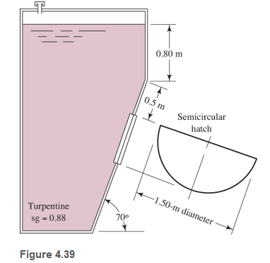
Chapter 4, Problem 4.27PP
Refer to Fig.4.39
Expert Solution & Answer
Want to see the full answer?
Check out a sample textbook solution
Students have asked these similar questions
What is the moment of Inertia of this body? What is Ixx, Iyy, and Izz
i need the The shaft is supported by a smooth thrust bearing at AA and a smooth journal bearing at BB. Draw the shear diagram for the shaft. Follow the sign convention.
4- In the system shown in the figure, the water velocity in the 12 in. diameter
pipe is 8 ft/s. Determine the gage reading at position 1.
Elevation 170 ft
1
Elevation 200 ft |
8 ft, 6-in.-diameter,
150 ft, 12-in.-diameter,
f = 0.020
f = 0.020
A
B
Hints: the minor losses should consider the contraction loss at A and the
expansion loss at B.
Chapter 4 Solutions
Applied Fluid Mechanics: Global Edition
Ch. 4 - figure 4.2 shows a vacuum tank with a flat...Ch. 4 - The flat left end of the tank shown in Fig. 4.21...Ch. 4 - An exhaust system for a room creates a partial...Ch. 4 - A piece of 14 -in Schedule 40 pipe is used as a...Ch. 4 - A pressure relief valve is designed so that the...Ch. 4 - A gas-powered cannon shoots projectiles by...Ch. 4 - The egress hatch of a manned spacecraft is...Ch. 4 - A tank containing liquid ammonia at 77F has a flat...Ch. 4 - The bottom of a laboratory vat has a hole in it to...Ch. 4 - A simple shower for remote locations is designed...
Ch. 4 - Calculate the total force on the bottom of the...Ch. 4 - If the length of the tank in Fig. 4.24 is 1.2m,...Ch. 4 - An observation port in a small submarine is...Ch. 4 - A rectangular gate is installed in a vertical wall...Ch. 4 - '4.15 A vat has a sloped side, as shown in Fig....Ch. 4 - The wall shown in Fig. 4.28 is 20 ft long, (a)...Ch. 4 - If the wall in Fig. 4.29 is 4m long, calculate the...Ch. 4 - Refer to Fig. 4.30Ch. 4 - Refer to Fig. 4.31Ch. 4 - Refer to Fig.4.32Ch. 4 - Refer to Fig 4.33Ch. 4 - Refer to Fig. 4.34Ch. 4 - Refer to Fig. 4.35 (?Ch. 4 - Swimming poo!WilierGlasswindow2 ft diameterFigure...Ch. 4 - 4.25 Refer to Fig 4.37Ch. 4 - Refer to Fig.4.38Ch. 4 - Refer to Fig.4.39Ch. 4 - Refer to Fig.4.40Ch. 4 - Refer to Fig 4.41Ch. 4 - figure 4.42i5 shows a gasoline tank filled into...Ch. 4 - If the tank in Fig. 4.42 is filled just to the...Ch. 4 - If the tank in Fig. 4.42 is only half full of...Ch. 4 - For the water tank shown in Fig. 4.43, compute the...Ch. 4 - For the water tank shown in Fig. 4.43, compute the...Ch. 4 - For the water tank shown in Fig. 4.43, compute the...Ch. 4 - For the orange-drink tank shown in Fig. 4.32,...Ch. 4 - For the orange-drink tank shown in Fig. 4.32,...Ch. 4 - For the oil tank shown in Fig. 4.35, compute the...Ch. 4 - For the oil tank shown in Fig. 4.35; compute the...Ch. 4 - figure 4.44 shows a rectangular gate holding water...Ch. 4 - figure 4.45 shows a gate hinged at its bottom and...Ch. 4 - figure 4.46 shows a tank of water with a circular...Ch. 4 - Repeat Problem 4.19(Fig. 4.31), except that the...Ch. 4 - Repeat Problem 4.22 (Fig. 4.32), except that the...Ch. 4 - Repeat Problem 4.26 (Fig. 4.38 ). except that the...Ch. 4 - Repeat Problem 4.28 (Fig. 4.40 ), except that the...Ch. 4 - Use Fig 4.47. The surface is 2.00m long.Ch. 4 - Use Fig.4.48. The surface is 2.50m long.Ch. 4 - Use Fig.4.49. The surface is 5.00 ft longCh. 4 - Use Fig.4.50. The surface is 4.50 ft long.Ch. 4 - Use Fig.4.51.The surface is 4.00 m long.Ch. 4 - Use Fig .4.52. The surface is 1.50m longCh. 4 - Use Fig. 4.53. The surface is 1.50m long.Ch. 4 - Use Fig. 4.54. The surface is 60 in longCh. 4 - Repeat Problem 4.47 using Fig. 4.47, except that...Ch. 4 - Repeat Problem 4.48 using Fig. 4.48, except that...Ch. 4 - The tank in Fig. 4.55 has a view port in the...Ch. 4 - Insulated concrete forms (ICFs) are becoming more...Ch. 4 - Lacks are installed in rivers to allow boats to...Ch. 4 - When a dam is installed in a river that has...Ch. 4 - A wealthy eccentric is interested in having an...Ch. 4 - A pneumatic cylinder like the one shown in Fig....Ch. 4 - Determine the magnitude and the location of the...Ch. 4 - For the hinged gate shown in Fig. 4.61, determine...Ch. 4 - Prob. 4.65PPCh. 4 - Write a program to solve Problem 4.41 with any...Ch. 4 - Write a program to solve Problem 4.42 (Fig. 4.46)...Ch. 4 - Write a program to solve curved surface problems...Ch. 4 - For Program 1, cause the depth h to vary over some...
Additional Engineering Textbook Solutions
Find more solutions based on key concepts
Comprehension Check 7-14
The power absorbed by a resistor can be given by P = I2R, where P is power in units of...
Thinking Like an Engineer: An Active Learning Approach (4th Edition)
Porter’s competitive forces model: The model is used to provide a general view about the firms, the competitors...
Management Information Systems: Managing The Digital Firm (16th Edition)
What types of coolant are used in vehicles?
Automotive Technology: Principles, Diagnosis, And Service (6th Edition) (halderman Automotive Series)
How are relationships between tables expressed in a relational database?
Modern Database Management
1.2 Explain the difference between geodetic and plane
surveys,
Elementary Surveying: An Introduction To Geomatics (15th Edition)
Knowledge Booster


Learn more about
Need a deep-dive on the concept behind this application? Look no further. Learn more about this topic, mechanical-engineering and related others by exploring similar questions and additional content below.Similar questions
- What is the moment of Inertia of this body? What is Ixx, Iyy, and Izzarrow_forwardConsider a glass window (Hight = 1.2 m, Width = 2 m). The room thatfaces the window are maintained at 25 o C. The average temperature ofthe inner surface of the window is 5 o C. Calculate the total heat transferrate from through the window a) IdenCfy what type(s) of convecCon is important (circle one). • external forced (Chapter 7)• internal forced (Chapter 8)• natural convecCon (Chapter 9)• boiling and condensaCon (Chapter 10)b) IdenCfy the necessary equaCon(s) needed to solve the problem. c) IdenCfy important fluid properCes you need to solve the problem. d) Calculate the total heat transferred.arrow_forwardWater is condensing on a square plate (0.5 m x 0.5 m) placed verCcally. If the desired rate ofcondensaCon is 0.016 kJ/s, determine the necessary surface temperature of the plate at atmosphericpressure. Assume the film temperature of 90 o C for evaluaCon of fluid properCes of water and thesurface temperature of 80 o C for the evaluaCon of modified latent heat of vaporizaConarrow_forward
- Water at 20 o C enters the 4 cm-diameter, 14 m-long tube at a rate of 0.8 kg/s. The surfacetemperature of the pipe is maintained at 165 o Cby condensing geothermal stream at the shellside of the heat exchanger. Use water properCesat 85 o C for all calculaCons.(a) Show that the water flow is turbulent and thermally fully developed. (b) EsCmate the heat transfer coefficient for convecCve heat transfer from the pipe to the water. For a fully developed turbulent flow within the smooth pipe, the Nu number can becalculated from the following equaCon:(c) Calculate the exit temperature of the water. (d) Share your opinion on whether the use of water properties at 85°C is appropriate. Yes or No because:arrow_forwardConsider a hot automotive engine, which can beapproximated as a 0.5-m-high, 0.40-m-wide, and 0.8-m-long rectangular block. The bottom surface of the block isat a temperature of 100°C and has an emissivity of 0.95.The ambient air is at 20°C, and the road surface is at25°C. Determine the rate of heat transfer from the bottomsurface of the engine block by convection and radiationas the car travels at a velocity of 80 km/h. Assume theflow to be turbulent over the entire surface because of theconstant agitation of the engine block. a) Calculate convective heat transfer coefficient (h). b) Calculate the total heat transfer ratearrow_forward8 mm- Top view -200 mm-180 mm- D B B 12 mm Side view B -8 mm D PROBLEM 1.56 In an alternative design for the structure of Prob. 1.55, a pin of 10-mm-diameter is to be used at A. Assuming that all other specifications remain unchanged, determine the allowable load P if an overall factor of safety of 3.0 is desired. PROBLEM 1.55 In the structure shown, an 8- mm-diameter pin is used at A, and 12-mm- diameter pins are used at B and D. Knowing that the ultimate shearing stress is 100 MPa at all connections and that the ultimate normal stress is 250 MPa in each of the two links joining B and D, determine the allowable load P if an overall factor of safety of 3.0 is desired. 20 mm P 8 mm- 12 mm- Front viewarrow_forward
- Where on the beam below is the Maximum Deflection likely to occur? 2P A "ती Point A Point B Point C Point D Point B or Point D ८ B पarrow_forwardSign in ||! PDE 321 proje X IMB321 PDF Lecture 5 X PDF Planet Ec X PDF Planet Ec X PDF PEABWX PDF meeting x PDF GSS Quo X PDF File C:/Users/KHULEKANI/Downloads/CIVE%20281%20Ass-2.pdf Draw | | All | a | Ask Copilot + 1 of 7 | D SOLUTION B PROBLEM 12.16 Block 4 has a mass of 40 kg, and block B has a mass of 8 kg. The coefficients of friction between all surfaces of contact are μ, = 0.20 H = 0.15. Knowing that P = 50 N→, determine (a) the acceleration of block B, (b) the tension in the cord. Constraint of cable: 2x + (x-x1) = x + x = constant. a+ag = 0, or aB = -a Assume that block A moves down and block B moves up. Block B: +/ΣF, = 0: NAB - WB cos 0 = 0 =ma: -T+μN + Wsin = We as g + ΣΕ We Eliminate NAB and aB- NAB B Nas HN UNA A NA -T+W(sin+μcоsе) = WB- g VD"M- g Block A: +/ΣF, = 0: NA-NAB - W₁cos + Psinė = 0 N₁ = N AB+W cose - Psin = (WB+WA)cose - Psinė ΣF=ma -T+Wsino-FAB-F + Pcos = CIVE 281 X + Ждал g Q | го || حالم ☑arrow_forwardWhere on the below beam is the Maxiumum Slope likely to occur? 120 Point A Point B Point C Point B or Point C B сarrow_forward
- A very thin metallic sheet is placed between two wood plates of different thicknesses. Theplates are firmly pressed together and electricity is passed through the sheet. The exposed surfaces ofthe two plates lose heat to the ambient fluid by convection. Assume uniform heating at the interface.Neglect end effects and assume steady state.[a] Will the heat transfer through the two plates be the same? Explain.[b] Will the exposed surfaces be at the same temperature? Explainarrow_forwardDesign consideration requires that the surface of a small electronic package be maintained at atemperature not to exceed 82 o C. Noise constraints rule out the use of fans. The power dissipated inthe package is 35 watts and the surface area is 520 cm2 . The ambient temperature and surroundingwalls are assumed to be at 24 o C. The heat transfer coefficient is estimated to be 9.2 W/m2- oC andsurface emissivity is 0.7. Will the package dissipate the required power without violating designconstraints?arrow_forwardConsider radiation from a small surface at 100 oC which is enclosed by a much larger surface at24 o C. Determine the percent increase in the radiation heat transfer if the temperature of the smallsurface is doubled.arrow_forward
arrow_back_ios
SEE MORE QUESTIONS
arrow_forward_ios
Recommended textbooks for you
 Elements Of ElectromagneticsMechanical EngineeringISBN:9780190698614Author:Sadiku, Matthew N. O.Publisher:Oxford University Press
 Mechanics of Materials (10th Edition)Mechanical EngineeringISBN:9780134319650Author:Russell C. HibbelerPublisher:PEARSON
 Thermodynamics: An Engineering ApproachMechanical EngineeringISBN:9781259822674Author:Yunus A. Cengel Dr., Michael A. BolesPublisher:McGraw-Hill Education
 Control Systems EngineeringMechanical EngineeringISBN:9781118170519Author:Norman S. NisePublisher:WILEY
 Mechanics of Materials (MindTap Course List)Mechanical EngineeringISBN:9781337093347Author:Barry J. Goodno, James M. GerePublisher:Cengage Learning
 Engineering Mechanics: StaticsMechanical EngineeringISBN:9781118807330Author:James L. Meriam, L. G. Kraige, J. N. BoltonPublisher:WILEY
Elements Of Electromagnetics
Mechanical Engineering
ISBN:9780190698614
Author:Sadiku, Matthew N. O.
Publisher:Oxford University Press
Mechanics of Materials (10th Edition)
Mechanical Engineering
ISBN:9780134319650
Author:Russell C. Hibbeler
Publisher:PEARSON
Thermodynamics: An Engineering Approach
Mechanical Engineering
ISBN:9781259822674
Author:Yunus A. Cengel Dr., Michael A. Boles
Publisher:McGraw-Hill Education
Control Systems Engineering
Mechanical Engineering
ISBN:9781118170519
Author:Norman S. Nise
Publisher:WILEY
Mechanics of Materials (MindTap Course List)
Mechanical Engineering
ISBN:9781337093347
Author:Barry J. Goodno, James M. Gere
Publisher:Cengage Learning
Engineering Mechanics: Statics
Mechanical Engineering
ISBN:9781118807330
Author:James L. Meriam, L. G. Kraige, J. N. Bolton
Publisher:WILEY
How to Measure Threads; Author: PracticalMachinist;https://www.youtube.com/watch?v=Uuy7EViS7Kc;License: Standard Youtube License