
Concept explainers
Videos
Figure 4.34 shows double-circuit conductors' relative positions in segment I of transposition of a completely transposed three-phase overhead transmission line. The inductance is given by
Where
With mean distances defined by equivalent spacings

And
Now consider a 345-kV, three-phase, double-circuit line with phase-conductor’s GMR of 0.0588 ft and the horizontal conductor configuration shown in Figure 4.35.
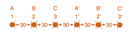
- Determine the inductance per meter per phase in Henries (H).
- Calculate the inductance of just one circuit and then divide by 2 to obtain the inductance of the double circuit.
Want to see the full answer?
Check out a sample textbook solution
Chapter 4 Solutions
Power System Analysis & Design


- 8- is flip-flop which indicates some condition which arises after the execution of an arithmetic or logic instruction. a) Status flag b) Instruction registers c) Temporary register d) None of these 9- El instruction is a_ a) Branching Instructions b) Logical Instructions c) Control Instructions d) Data Transfer Instruction e) Arithmetic Instructionsarrow_forward1. Write a program to add 4 hex numbers located in the memory locations 2001h, 2002h, 2003h, 2004h and store the result at location 2005harrow_forwardnot use ai pleasearrow_forward
- 17- In 8085 name the 16 bit registers. a) Program Counter b) Stack Pointer c) a and b d) Instruction Register 18- In response to RST 7.5 interrupt, the execution of control transfers to memory location. a) 0000H b) 003CH c) 002CH d) 0034H 19- Let contents of accumulator and B are 00000100 and 01000000 respectively. After execution of SUB B instruction, accumulator contents are a) 11000100 b) 01000000 c) 010001000 d) 00000100arrow_forward1.) A single instruction to clear the lower 4 bits of accumulator in 8085 alp is, a) XRI FOH b) XRI OFH c) ANI OFH d) ANI FO 2.) The status of Z, AC, CY flags after execution of following instructions are, MVI A, A9H MVI B, 57H ADD B HLT a) 0,1,1 b) 1,0,0 c) 1,1,1 d) 1,0,1 3.) Consider the loop: LXI H 000A MVI C OB LOOP: DCX H DCR C JNZ LOOP HLT This loop will be executed by: a) infinite times b) 11 time c) 10 times d) 1 timearrow_forwardFundamentals Of Energy Systems HW 6 Q6arrow_forward
- Fundamentals Of Energy Systems HW 6 Q4arrow_forward1. For the 2-dimensional lattice shown in the following figure, using the two sets of given primitive translation vectors to write the translation vectors that can translate lattice point A to point B. (10 pts) (1) (2) (1) T= (2) T T=arrow_forwardFundamentals Of Energy Systems HW 6 Q5arrow_forward
 Power System Analysis and Design (MindTap Course ...Electrical EngineeringISBN:9781305632134Author:J. Duncan Glover, Thomas Overbye, Mulukutla S. SarmaPublisher:Cengage Learning