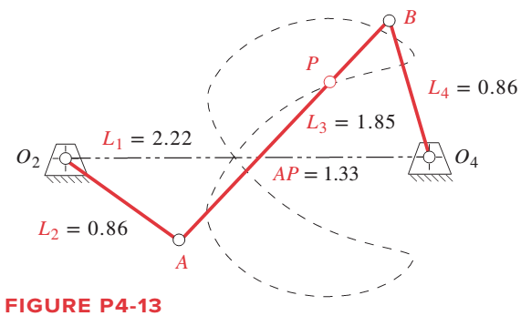
For the linkage in Figure P4-13, find its limit (toggle) positions in terms of the angle of link O 4 B referenced to the line of centers O 4 O 2 when driven from link O 4 B . Then calculate and plot the angular displacement of links 2 and 3 and the path coordinates of point P between those limits, with respect to the angle of the input crank O 4 B over its possible range of motion referenced to the line of centers O 4 O 2 .
For the linkage in Figure P4-13, find its limit (toggle) positions in terms of the angle of link O 4 B referenced to the line of centers O 4 O 2 when driven from link O 4 B . Then calculate and plot the angular displacement of links 2 and 3 and the path coordinates of point P between those limits, with respect to the angle of the input crank O 4 B over its possible range of motion referenced to the line of centers O 4 O 2 .
Solution Summary: The author explains how to design linkO2A limiting locations and angular displacement for a given mechanism.
For the linkage in Figure P4-13, find its limit (toggle) positions in terms of the angle of link
O
4
B
referenced to the line of centers
O
4
O
2
when driven from link
O
4
B
. Then calculate and plot the angular displacement of links 2 and 3 and the path coordinates of point P between those limits, with respect to the angle of the input crank
O
4
B
over its possible range of motion referenced to the line of centers
O
4
O
2
.
An AISI 1018 steel ball with 1.100-in diameter is used as a roller between a flat plate
made from 2024 T3 aluminum and a flat table surface made from ASTM No. 30 gray
cast iron. Determine the maximum amount of weight that can be stacked on the
aluminum plate without exceeding a maximum shear stress of 19.00 kpsi in any of the
three pieces. Assume the figure given below, which is based on a typical Poisson's
ratio of 0.3, is applicable to estimate the depth at which the maximum shear stress
occurs for these materials.
1.0
0.8
Ratio of stress to Pmax
0.4
90
0.6
στ
Tmax
0.2
0.5a
a
1.5a
2a
2.5a
За
Distance from contact surface
The maximum amount of weight that can be stacked on the aluminum plate is
lbf.
A carbon steel ball with 27.00-mm diameter is pressed together with an aluminum ball
with a 36.00-mm diameter by a force of 11.00 N. Determine the maximum shear
stress and the depth at which it will occur for the aluminum ball. Assume the figure
given below, which is based on a typical Poisson's ratio of 0.3, is applicable to estimate
the depth at which the maximum shear stress occurs for these materials.
1.0
0.8
Ratio of stress to Pma
9 0.6
στ
24
0.4
Tmax
0.2
0
0.5a
a
1.5a
Z
2a
2.5a
За
Distance from contact surface
The maximum shear stress is determined to be
MPa.
The depth in the aluminum ball at which the maximum shear stress will occur is
determined to be [
mm.
Need a deep-dive on the concept behind this application? Look no further. Learn more about this topic, mechanical-engineering and related others by exploring similar questions and additional content below.


 Elements Of ElectromagneticsMechanical EngineeringISBN:9780190698614Author:Sadiku, Matthew N. O.Publisher:Oxford University Press
 Mechanics of Materials (10th Edition)Mechanical EngineeringISBN:9780134319650Author:Russell C. HibbelerPublisher:PEARSON
 Thermodynamics: An Engineering ApproachMechanical EngineeringISBN:9781259822674Author:Yunus A. Cengel Dr., Michael A. BolesPublisher:McGraw-Hill Education
 Control Systems EngineeringMechanical EngineeringISBN:9781118170519Author:Norman S. NisePublisher:WILEY
 Mechanics of Materials (MindTap Course List)Mechanical EngineeringISBN:9781337093347Author:Barry J. Goodno, James M. GerePublisher:Cengage Learning
 Engineering Mechanics: StaticsMechanical EngineeringISBN:9781118807330Author:James L. Meriam, L. G. Kraige, J. N. BoltonPublisher:WILEY