
Find the force in each bar and mention the force is tension or compression of the bars in the truss.
Explanation of Solution
Assumptions:
- Consider the state of bars as tension (T) where the force is pulling the bar and as compression (C) where the force is pushing the bar.
- The sign of the force in the bar is positive when the force is in tension and negative when the force is in compression.
- Consider the force indicating right side as positive and left side as negative in horizontal components of forces.
- Consider the force indicating upward is taken as positive and downward as negative in vertical components of forces.
- Consider clockwise moment as negative and anti-clock wise moment as positive wherever applicable.
Show the free-body diagram of the entire truss as in Figure 1.
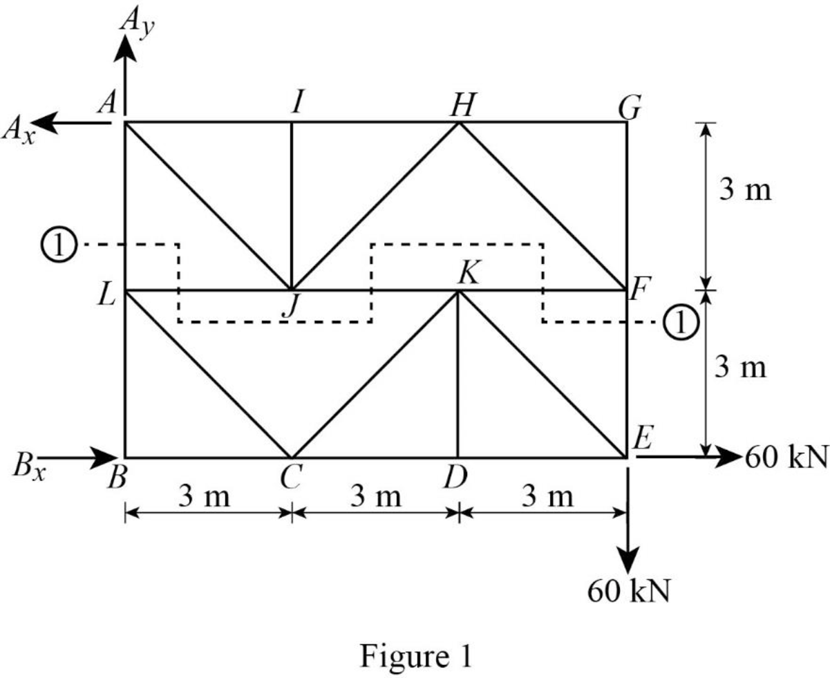
Find the horizontal reaction at point B by taking moment about point A.
Find the vertical reaction at point A by resolving the vertical component of forces.
Find the horizontal reaction at point A by resolving the horizontal component of forces.
Find the zero force bars in the truss.
By observation, the zero force bars are HG, GF, IF, KD, and LB.
Pass a section 1-1 as in Figure 1.
Consider the lower portion of the section 1-1.
Show the free-body diagram of the lower portion 1-1 as in Figure 2.
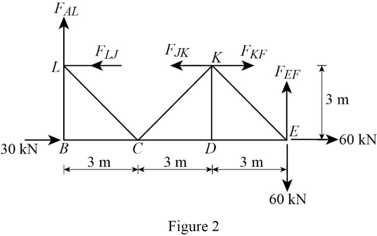
Find the force in the member EF by taking moment about the joint L.
Consider the joint E;
Show the forces acting at the joint E as in Figure 3.
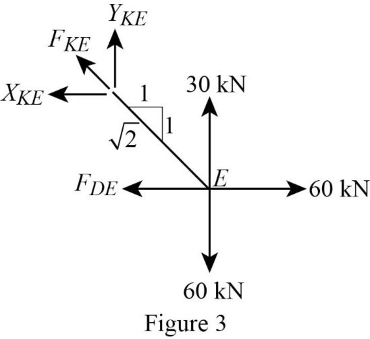
Resolve the vertical component of forces.
Use the proportion:
Resolve the horizontal component of forces.
Consider the joint D;
Show the forces acting at the joint D as in Figure 4.
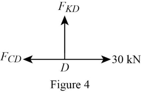
Resolve the vertical component of forces.
Resolve the horizontal component of forces.
Consider the joint F;
Show the forces acting at the joint F as in Figure 5.
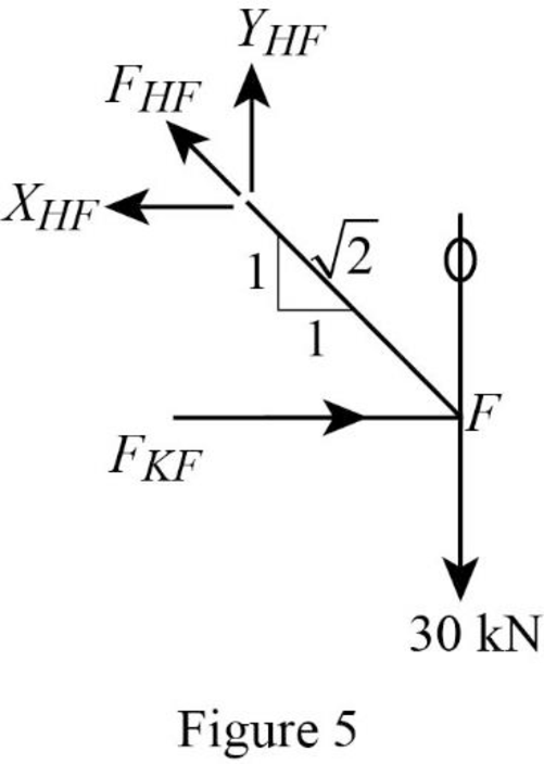
Resolve the vertical component of forces.
Use the proportion:
Resolve the horizontal component of forces.
Consider the joint H;
Show the forces acting at the joint H as in Figure 6.
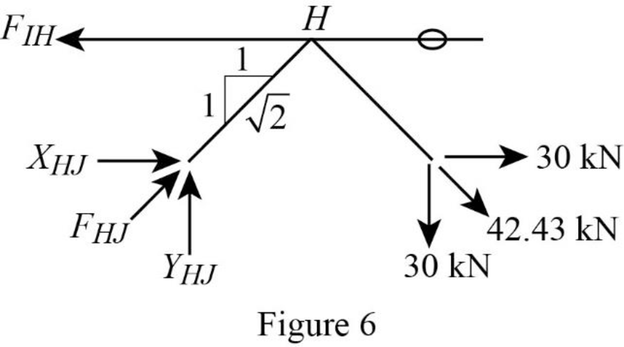
Resolve the vertical component of forces.
Use the proportion;
Resolve the horizontal component of forces.
Consider the joint I;
Show the forces acting at the joint I as in Figure 7.
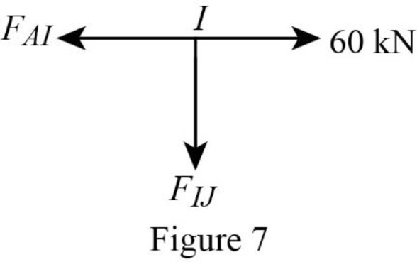
Resolve the vertical component of forces.
Resolve the horizontal component of forces.
Consider the joint K;
Show the forces acting at the joint K as in Figure 8.
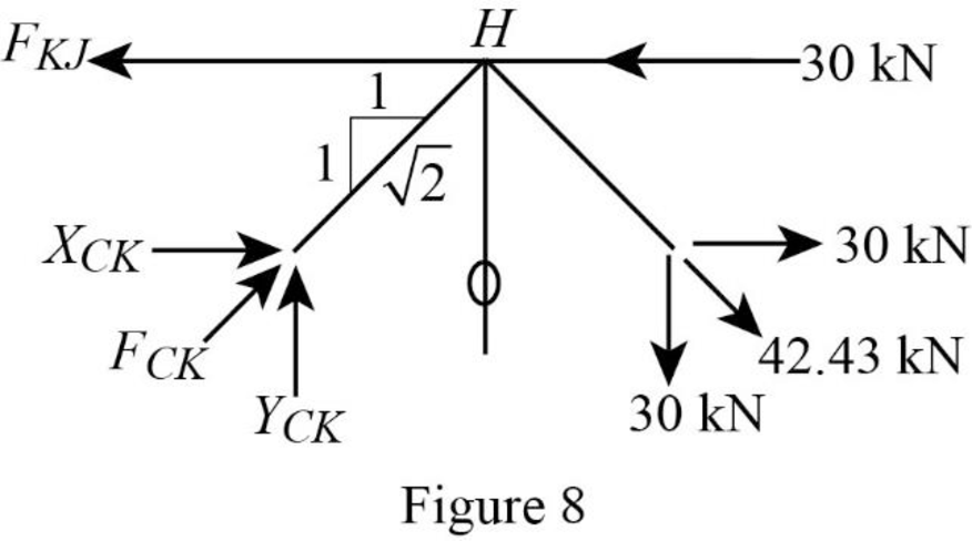
Resolve the vertical component of forces.
Use the proportion;
Resolve the horizontal component of forces.
Consider the joint C;
Show the forces acting at the joint C as in Figure 9.
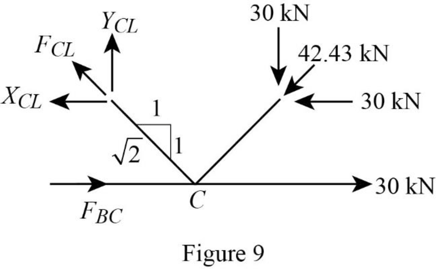
Resolve the vertical component of forces.
Use the proportion;
Resolve the horizontal component of forces.
Consider the joint J;
Show the forces acting at the joint J as in Figure 10.
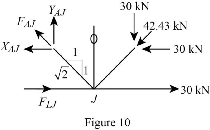
Resolve the vertical component of forces.
Use the proportion;
Resolve the horizontal component of forces.
Consider the joint L;
Show the forces acting at the joint L as in Figure 11.
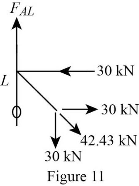
Resolve the vertical component of forces.
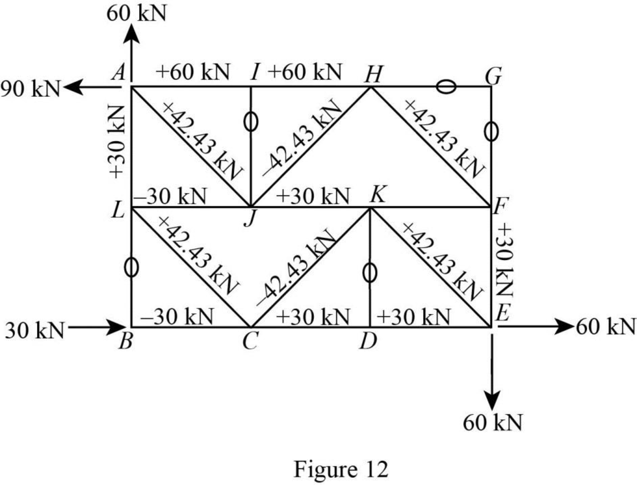
Show the forces in the bars of the truss as in Figure 12.
Want to see more full solutions like this?
Chapter 4 Solutions
UCD FUND OF STRUCTURAL ANALYSIS 5E

- I need detailed help solving this exercise from homework of Engineering Mathematics II.I do not really understand how to do, please do it step by step, not that long but clear. Thank you!P.S.: Please do not use AI, thanks!arrow_forwardI need solution by handarrow_forwardI need detailed help solving this exercise from homework of Engineering Mathematics II.I do not really understand how to do, please do it step by step, not that long but clear. Thank you!P.S.: Please do not use AI, thanks!arrow_forward
- I need detailed help solving this exercise from homework of Engineering Mathematics II.I do not really understand how to do, please do it step by step, not that long but clear. Thank you!P.S.: Please do not use AI, thanks!arrow_forwardI need detailed help solving this exercise from homework of Engineering Mathematics II.I do not really understand how to do, please do it step by step, not that long but clear. Thank you!P.S.: Please do not use AI, thanks!arrow_forwardQ1: By using the PERT technique, the durations of the activities were calculated as shown in the table below, Draw an activity network for project by using Activity On Node (AON) method and find: 1. The project's total duration and date of completion and CP (assume the project start date is the 1st of June 2025)? 2. The overall variance of the project? 3. The probability of completing the project in 30 days? 4. The probability of completing the project in 22th of June 2025? 5. With a probability of 75%, what is the expected duration and date for completing the project? Activity Preceding activity K Optimistic duration (day) 4 Most likely duration (day) Pessimistic duration (day) 5 12 L 5 M K 5 11 8 17 11 N K 3 4 11 0 L 2 3 10 P M,N 4 7 10 Q N 3 7 17 R N,O 6 9 18 S P,Q,R 1 3 5arrow_forward
- I need detailed help solving this exercise from homework of Engineering Mathematics II.I do not really understand how to do, please do it step by step, not that long but clear. Thank you!P.S.: Please do not use AI, thanks!arrow_forwardI need solution by handarrow_forwardQ2: For the activities shown in the table below, it is required to reduce the total duration of the project four days by using crash program and network diagram, If you knew that indirect costs is 150 S/day and the delay fine is 100 $/day after the 14th day. Find new cost after crashing the project four days? Activity Preceding Normal Program Crash Program activity Duration (days) Direct Cost (S) Duration (days) Direct Cost (S) A 5 600 3 950 B - 4 200 3 500 C A 5 300 4 500 D A 2 600 1 615 E B 6 900 5 1025 800 3 F C 4 700 450 G D 4 400 3 700 3 700 1400 3 H E 2 600 I F,G,H 4 5000 Σ (40 px) good luck)arrow_forward
- I need detailed help solving this exercise from homework of Engineering Mathematics II.I do not really understand how to do, please do it step by step, not that long but clear. Thank you!P.S.: Please do not use AI, thanks!arrow_forwardDetermine the stiffness matrix of the frame as shown in Fig. 4. Nodes 1 and 3 are fixed supports. Assume I = 300(10^6) mm4, A = 10(10^3) mm2, E = 200 GPa for each member. Indicate the degrees-of freedom in all the stiffness matrices. Use the values of L3=2.5m, L4=4.5m, w=12kN/m and P=10kN. Please show all working and explain how the code numbers for global matrix are determined in detail.arrow_forwardI need detailed help solving this exercise from homework of Engineering Mathematics II.I do not really understand how to do, please do it step by step, not that long but clear. Thank you!P.S.: Please do not use AI, thanks!arrow_forward

 Structural Analysis (10th Edition)Civil EngineeringISBN:9780134610672Author:Russell C. HibbelerPublisher:PEARSON
 Principles of Foundation Engineering (MindTap Cou...Civil EngineeringISBN:9781337705028Author:Braja M. Das, Nagaratnam SivakuganPublisher:Cengage Learning
 Fundamentals of Structural AnalysisCivil EngineeringISBN:9780073398006Author:Kenneth M. Leet Emeritus, Chia-Ming Uang, Joel LanningPublisher:McGraw-Hill Education
 Traffic and Highway EngineeringCivil EngineeringISBN:9781305156241Author:Garber, Nicholas J.Publisher:Cengage Learning