
Concept explainers
Videos
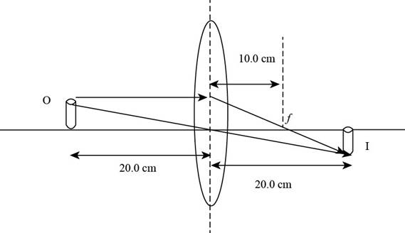
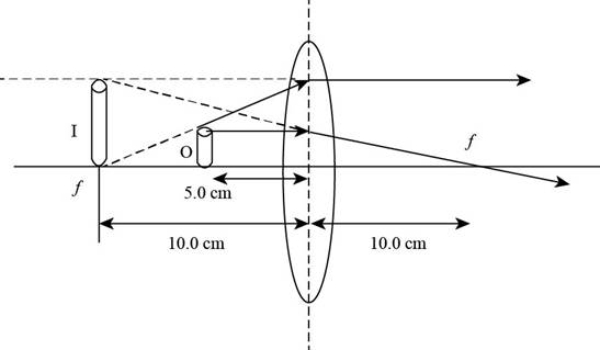
A converging lens has a focal length of 10.0 cm. Construct accurate ray diagrams for object distances of (i) 20.0 cm and (ii) 5.00 cm. (a) From your ray diagrams, determine the location of each image. (b) Is the image real or virtual? (c) Is the image upright or inverted? (d) What is the magnification of the image? (c) Compare your results with the values found algebraically. (f) Comment on difficulties in constructing the graph that could lead to differences between the graphical and algebraic answers.
(i)
To draw: The ray diagram for the given focal lengthy of the lens and the given object distance.
Answer to Problem 36.44P
Explanation of Solution
Introduction:
In a ray diagram in the case of lens or mirror the image is formed where two at least refracted or reflected rays coincide with each other.
Explanation:
Given info: The position of object is at
The ray diagram is shown in the figure below.

Figure (1)
(ii)
To draw: The ray diagram for the given focal length of the lens and the given object distance.
Answer to Problem 36.44P
Explanation of Solution
Introduction:
In a ray diagram in the case of lens or mirror the image is formed where two at least refracted or reflected rays coincide with each other.
Explanation:
Given info: The position of object is at
The ray diagram is shown in the figure below.

Figure (2)
(a)
Answer to Problem 36.44P
Explanation of Solution
From Figure (1), it is evident that the image is formed on the rear end of the lens and the image distance measured is
From Figure (2), the image is formed at
Conclusion:
Therefore, the measured distance for the image for the case when object is at
(b)
Answer to Problem 36.44P
Explanation of Solution
From Figure (1), it is evident that the image is formed on the rear side and is real and the images formed at the back side of the lens are real.
From Figure (2), the image is formed at
Conclusion:
The images formed by the lens in front of it are virtual and erect and images formed on the back side are real and inverted. Hence, image formed by the object kept at.
(c)
Answer to Problem 36.44P
Explanation of Solution
From Figure (1), it is evident that the image is formed on the rear side and is real. and
the real images are always inverted
From Figure (2), the image is formed at
The virtual images are always upright.
Conclusion:
Therefore, the images formed by the lens in front of it are virtual and erect and images formed on the back side are real and inverted. Hence, image formed by the object kept at.
(d)
Answer to Problem 36.44P
Explanation of Solution
Formula to calculate the magnification is
For the object at
For the object at the distance of
Conclusion:
Therefore, for the case of object at
(e)
Answer to Problem 36.44P
Explanation of Solution
Given Info: The focal length of the give lens is
From Figure (1) the image distance for the object at
For algebraic calculation, the formula for the image distance is,
Here,
Substitute
Form figure (1) the magnification is
Formula to calculate the magnification of the image
Here
Substitute
From figure (2) the image distance is
From equation (4) formula to calculate the image distance is,
Substitute
The image distance is
From equation (6) the formula to calculate the magnification is,
Substitute
From equation (6) and equation (7) it is evident that for the case of object at
From equation (8) and (9) the image distance and magnification is same for the ray diagram and the algebraic case when the object is
Conclusion:
Therefore, the result for the ray diagrams and algebraic calculations are same.
(f)
Answer to Problem 36.44P
Explanation of Solution
While drawing the graph the possible errors are human hand errors, parallax errors and scale measurement errors.
Human Hand Errors are while making the ray diagrams the rays might not converge with extreme precision. Parallax error/Human eye errors occur due to human eye. Scale errors are during the scale measurement.
Conclusion:
Therefore, the three most common errors that can lead to difficulties in constructing the graph which might lead to change the algebraic and graphical values are human hand errors, parallax errors and Scale errors.
Want to see more full solutions like this?
Chapter 36 Solutions
EBK PHYSICS FOR SCIENTISTS AND ENGINEER


- Certain types of particle detectors can be used to reconstruct the tracks left by unstable, fast-moving sub-atomic particles. Assume that a track with a length of L=2.97 mm in the laboratory frame of reference has been observed. Further assume that you determined from other detector data that the particle moved at a speed of L=0.910 ⚫ c, also in the laboratory frame of reference. c denotes the speed of light in vacuum. What proper lifetime would you determine for this particle from the data given? T= 4.0 Sarrow_forwardgenerated worksheetarrow_forwardWhile cruising down University Boulevard you are stopped by a cop who states that you ran a red traffic light. Because you don't want to pay the stiff fine, you are attempting a physics defense. You claim that due to the relativistic Doppler effect, the red color of the light λ=616 nm appeared green '=531 nm to you. The cop makes a quick calculation of his own and rejects your defense. How fast, in terms of your speed u divided by the speed of light in vacuum c, would you have to drive to justify your claim? Note that the speed u is taken to be a positive quantity. U 4.0 Carrow_forward
- 220 V is supplied to 800 primary turns of an autotransformer. What will the outputvoltage be across 200 secondary turns? 2. A filament transformer has a turns ratio of 1:20. What current must be supplied to theprimary windings if 5 A is required by the filament? 3. The filament transformer in the previous question is supplied with 150 V to theprimary side. What is the secondary voltage? 4. 440 V is supplied to 1000 primary turns of an autotransformer. If the desired outputvoltage is 100 V how many secondary turns must be tapped?arrow_forward220 volts is supplied across 1200 winding of the primary coil of the autotransformer.If 1650 windings are tapped, what voltage will be supplied to the primary coil of thehigh-voltage transformer?2. A kVp meter reads 86 kVp and the turns ratio of the high-voltage step-up transformeris 1200. What is the true voltage across the meter?3. The supply voltage from the autotransformer to the filament transformer is 60 volts. If theturns ratio of the filament transformer is 1/12, what is the filament voltage?4. If the current in the primary side of the filament transformer in question 3 were 0.5 A,what would be the filament current?5. The supply to a high-voltage step-up transformer with a turns ratio of 550 is 190 volts.What is the voltage across the x-ray tube?arrow_forward220 V is supplied to 800 primary turns of an autotransformer. What will the outputvoltage be across 200 secondary turns? 2. A filament transformer has a turns ratio of 1:20. What current must be supplied to theprimary windings if 5 A is required by the filament? 3. The filament transformer in the previous question is supplied with 150 V to theprimary side. What is the secondary voltage? 4. 440 V is supplied to 1000 primary turns of an autotransformer. If the desired outputvoltage is 100 V how many secondary turns must be tapped?arrow_forward
- Assume ax(u) is constant, then show thatarrow_forwardOne strain of bacteria was found to have a membrane potential of -120 mVmV at a pHpH of 7.5. A bacterium can be modeled as a 1.5-μmμm-diameter sphere. How many positive ions are needed on the exterior surface to establish this membrane potential? (There are an equal number of negative ions on the interior surface.) Assume that the membrane properties are the same as those of mammalian cells.arrow_forwardQ: Draw the fabrication layers of a transistor with metal and semiconductor MS junction (Schottkyj unction).arrow_forward
 Principles of Physics: A Calculus-Based TextPhysicsISBN:9781133104261Author:Raymond A. Serway, John W. JewettPublisher:Cengage Learning
 Physics for Scientists and Engineers: Foundations...PhysicsISBN:9781133939146Author:Katz, Debora M.Publisher:Cengage Learning
 University Physics Volume 3PhysicsISBN:9781938168185Author:William Moebs, Jeff SannyPublisher:OpenStax
 Physics for Scientists and EngineersPhysicsISBN:9781337553278Author:Raymond A. Serway, John W. JewettPublisher:Cengage Learning
 Physics for Scientists and Engineers with Modern ...PhysicsISBN:9781337553292Author:Raymond A. Serway, John W. JewettPublisher:Cengage Learning
 Physics for Scientists and Engineers, Technology ...PhysicsISBN:9781305116399Author:Raymond A. Serway, John W. JewettPublisher:Cengage Learning