EBK ELECTRIC MOTOR CONTROL
10th Edition
ISBN: 9780100784598
Author: Herman
Publisher: YUZU
expand_more
expand_more
format_list_bulleted
Concept explainers
Textbook Question
Chapter 34, Problem 7SQ
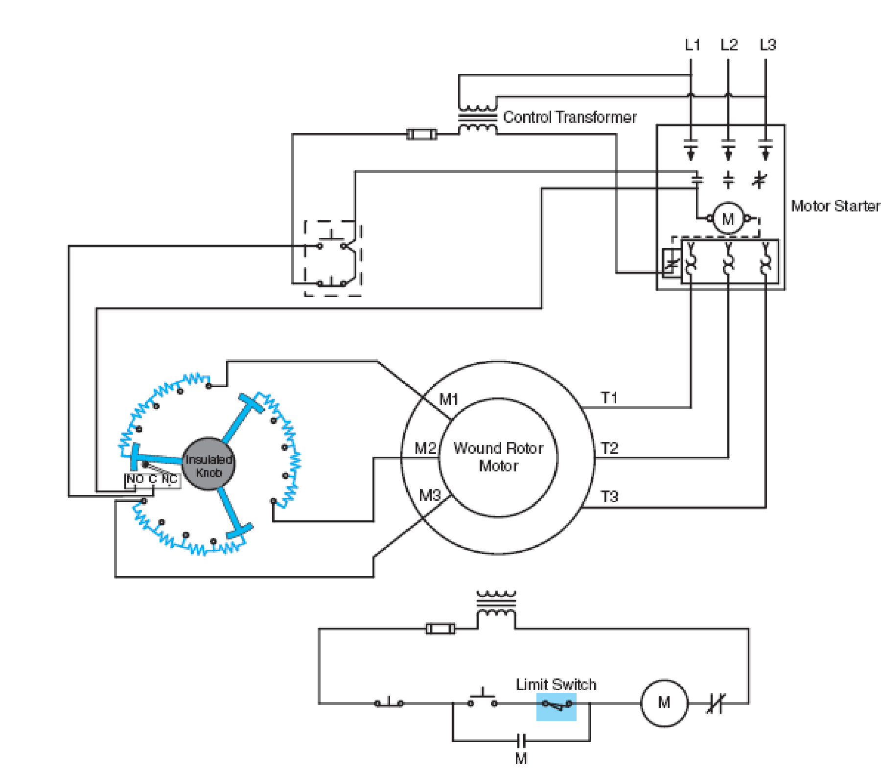
Refer to the basic control schematic in Figure 34–4. The limit switch is shown as
a. normally open.
b. normally closed.
c. normally open held closed.
d. normally closed held open.

Fig. 34–4 Wiring diagram of manual speed regulator interlocked with magnetic starter for control of slip ring motor (three-wire control).
Expert Solution & Answer
Want to see the full answer?
Check out a sample textbook solution
Students have asked these similar questions
Determine X(w) for the given function shown in Figure (1) by applying the
differentiation property of the Fourier Transform.
1
x(t)
Figure (1)
-1
1
2
5. Determine an expression for vo as a function of vs in the circuit shown below.
Assume the operational amplifier is ideal
(10 pts)
162
+
+
212
10052} -j 100-52
No
4. A 120 volt rms voltage source supplies 20 Amps rms to a load. The load requires
2,078 watts. What is the reactive power (Vars) and the power factor of the load.
Assume the load is inductive.
(15pts)
Chapter 34 Solutions
EBK ELECTRIC MOTOR CONTROL
Ch. 34 - What characteristic of wound rotor motors led to...Ch. 34 - Prob. 2SQCh. 34 - What other name is given to the wound rotor motor?Ch. 34 - Does increased resistance in the rotor circuit...Ch. 34 - Prob. 5SQCh. 34 - What is the difference between a manual faceplate...Ch. 34 - Refer to the basic control schematic in Figure...
Knowledge Booster
Learn more about
Need a deep-dive on the concept behind this application? Look no further. Learn more about this topic, electrical-engineering and related others by exploring similar questions and additional content below.Similar questions
- Draw a diagram for a UPS that takes in an input of 690Vac 3 phase and a output of 30kVA single phase.arrow_forwardCan you draw the computed panel board (2nd attached pic) like the panel board management (1st attached pic)? ps. not graded, i just want to know what it looks like when it draw.arrow_forwardFor the circuit shown, let Is = 5, R₁-40, R2-30, R3-100, R4-80, R5-40, R6-30, R7- 10, and Rg= 100, and find: R₂ R6 ww www VX R3 R7 R8 RI R₁₂ Rs R5 www • The voltage Vx" (V) ⚫ The power absorbed by the output resistor Rg: Power= {Hint: you can use current divider (CD) or any other method.} (W) Tarrow_forward
- For the circuit shown, let V₁ = 26, R1-30, R₂-40, R3-50, R4-20, R5-100, R6-10, and find: RA R5 R3 V (+) R₁ R₂ R6 www • The voltage v (V) • The power delivered by the power source Vs: Power= {Hint: you can use voltage divider (VD) or any other method.} (W)arrow_forwardIn the circuit shown, let R₁-7, R₂-12, R3-24, R4-2, V₁ =17, V2 -68, and V3-51, to calculate the power delivered (or absorbed) by the circuit inside the box, as follows: {NOTE: On Multiple Choice Questions, like this problem, you have only one attempt } 1. The current I is equal to (choose the closed values in amperes) -0.791 0 -0.756 3.022 0.756 (A) -3.022 0.791 2. The power delivered (or absorbed) (choose the closest value in watts) (W) 373.345 0 -373.345 -52.234 52.234 65.079 O-24.833 R₁ V₂ R3 R₂ www V3 V₁ www R4arrow_forwardDetermine X(w) for the given function shown in Figure (1) by applying the differentiation property of the Fourier Transform. x(t) Figure (1) -2 -1 1 2arrow_forward
- For a enahnced-type NMOS transistor with V₁=+1V and kn'(w/L)= 2 mA/V2, find the minimum VDs required to operate in the saturation region when VGS=+2 V. What is the corresponding value of ID?arrow_forward. Using Properties to find the Z-Transform including the region of convergence for x(n) = n (2)" cos(0.2π(n − 2))u(n − 1) - -arrow_forwardJ VDD M₁ In the circuit of figure shown below, determine the region of operation of M₁as Vigoes from VDD.to zero. (You may want to draw a plot or just explain by the range, remember the transistor is a PMOS) Assume VDD = 2.5 V and | VTH | = 0.4V. 5 + 1 Varrow_forward
arrow_back_ios
SEE MORE QUESTIONS
arrow_forward_ios
Recommended textbooks for you

 Delmar's Standard Textbook Of ElectricityElectrical EngineeringISBN:9781337900348Author:Stephen L. HermanPublisher:Cengage Learning
 Electricity for Refrigeration, Heating, and Air C...Mechanical EngineeringISBN:9781337399128Author:Russell E. SmithPublisher:Cengage Learning
 EBK ELECTRICAL WIRING RESIDENTIALElectrical EngineeringISBN:9781337516549Author:SimmonsPublisher:CENGAGE LEARNING - CONSIGNMENT


Delmar's Standard Textbook Of Electricity
Electrical Engineering
ISBN:9781337900348
Author:Stephen L. Herman
Publisher:Cengage Learning

Electricity for Refrigeration, Heating, and Air C...
Mechanical Engineering
ISBN:9781337399128
Author:Russell E. Smith
Publisher:Cengage Learning

EBK ELECTRICAL WIRING RESIDENTIAL
Electrical Engineering
ISBN:9781337516549
Author:Simmons
Publisher:CENGAGE LEARNING - CONSIGNMENT
How Thermistors Work - The Learning Circuit; Author: element14 presents;https://www.youtube.com/watch?v=g683mTSZ2i0;License: Standard Youtube License