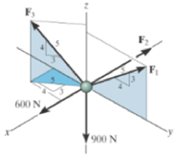
Determine the magnitude of forces F1, F2, F3, so that the particle is held in equilibrium.

Answer to Problem 7FP
The magnitude of force
The magnitude of force
The magnitude of force
Explanation of Solution
Given information:
The given force values are 600 N and 900 N.
Explanation:
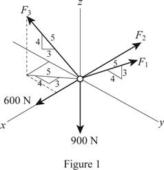
Show the free body diagram of the forces acting on the particle as in Figure 1.

Using Figure (1),
Determine the magnitude of forces using equation of equilibrium.
Force along x direction:
Force along y direction:
Force along z direction:
Conclusion:
Substitute
Thus, the magnitude of force
Substitute
Thus, the magnitude of force
Substitute
Thus, the magnitude of force
Want to see more full solutions like this?
Chapter 3 Solutions
Engineering Mechanics: Statics, Student Value Edition Plus Mastering Engineering with Pearson eText -- Access Card Package (14th Edition)
Additional Engineering Textbook Solutions
Management Information Systems: Managing The Digital Firm (16th Edition)
Electric Circuits. (11th Edition)
Concepts Of Programming Languages
Java How to Program, Early Objects (11th Edition) (Deitel: How to Program)
Java: An Introduction to Problem Solving and Programming (8th Edition)
Computer Science: An Overview (13th Edition) (What's New in Computer Science)
- What are the control hardware shown in the Figure?arrow_forwardQuestion 1. A tube rotates in the horizontal ry plane with a constant angular velocity w about the z-axis. A particle of mass m is released from a radial distance R when the tube is in the position shown. This problem is based on problem 3.2 in the text. R m 2R Figure 1 x a) Draw a free body diagram of the particle if the tube is frictionless. b) Draw a free body diagram of the particle if the coefficient of friction between the sides of the tube and the particle is = k = p. c) For the case where the tube is frictionless, what is the radial speed at which the particle leaves the tube? d) For the case where there is friction, derive a differential equation that would allow you to solve for the radius of the particle as a function of time. I'm only looking for the differential equation. DO NOT solve it. 1 e) If there is no friction, what is the angle of the tube when the particle exits? • Hint: You may need to solve a differential equation for the last part. The "potentially useful…arrow_forwardQuestion 2. A smooth uniform sphere of mass m and radius r is squeezed between two massless levers, each of length 1, which are inclined at an angle with the vertical. A mechanism at pivot point O ensures that the angles & remain the same at all times so that the sphere moves straight upward. This problem is based on Problem 3-1 in the text. P P r Figure 2 a) Draw appropriate freebody diagrams of the system assuming that there is no friction. b) Draw appropriate freebody diagrams of the system assuming that there is a coefficient of friction between the sphere and the right lever of μ. c) If a force P is applied between the ends of the levers (shown in the diagram), and there is no friction, what is the acceleration of the sphere when = 30°arrow_forward
- If you had a matrix A = [1 2 3; 4 5 6; 7 8 9] and a matrix B = [1 2 3], how would you cross multiply them i.e. what is the cross product of AxB. what would be the cross product of a dyadic with a vector?arrow_forwardProblem 3: The inertia matrix can be written in dyadic form which is particularly useful when inertia information is required in various vector bases. On the next page is a right rectangular pyramid of total mass m. Note the location of point Q. (a) Determine the inertia dyadic for the pyramid P, relative to point Q, i.e., 7%, for unit vectors ₁₁, 2, 3.arrow_forwardCan you solve for v? Also, what is A x uarrow_forward
- The external loads on the element shown below at the free end are F = 1.75 kN, P = 9.0 kN, and T = 72 Nm. The tube's outer diameter is 50 mm and the inner diameter is 45 mm. Given: A(the cross-sectional area) is 3.73 cm², Moment inertial I is 10.55 cm4, and J polar moment inertial is 21.1 cm4. Determine the following. (1) The critical element(s) of the bar. (2) Show the state of stress on a stress element for each critical element. -120 mm- Farrow_forwardA crate weighs 530 lb and is hung by three ropes attached to a steel ring at A such that the top surface is parallel to the xy plane. Point A is located at a height of h = 42 in above the top of the crate directly over the geometric center of the top surface. Use the dimensions given in the table below to determine the tension in each of the three ropes. 2013 Michael Swanbom ↑ Z C BY NC SA b x B у D Values for dimensions on the figure are given in the following table. Note the figure may not be to scale. Variable Value a 30 in b 43 in с 4.5 in The tension in rope AB is lb The tension in rope AC is lb The tension in rope AD is lbarrow_forwardThe airplane weighs 144100 lbs and flies at constant speed and trajectory given by 0 on the figure. The plane experiences a drag force of 73620 lbs. a.) If = 11.3°, determine the thrust and lift forces required to maintain this speed and trajectory. b.) Next consider the case where is unknown, but it is known that the lift force is equal to 7.8 times the quantity (Fthrust Fdrag). Compute the resulting trajectory angle - and the lift force in this case. Use the same values for the weight and drag forces as you used for part a. Уллу Fdrag 10. Ө Fthrust cc 10 2013 Michael Swanbom BY NC SA Flift Fweight The lift force acts in the y' direction. The weight acts in the negative y direction. The thrust and drag forces act in the positive and negative x' directions respectively. Part (a) The thrust force is equal to lbs. The lift force is equal to Part (b) The trajectory angle is equal to deg. The lift force is equal to lbs. lbs.arrow_forward
- The hoist consists of a single rope and an arrangement of frictionless pulleys as shown. If the angle 0 = 59°, determine the force that must be applied to the rope, Frope, to lift a load of 4.4 kN. The three-pulley and hook assembly at the center of the system has a mass of 22.5 kg with a center of mass that lies on the line of action of the force applied to the hook. e ΘΕ B CC 10 BY NC SA 2013 Michael Swanbom Fhook Note the figure may not be to scale. Frope = KN HO Fropearrow_forwardDetermine the tension developed in cables AB and AC and the force developed along strut AD for equilibrium of the 400-lb crate. x. 5.5 ft C 2 ft Z 2 ft D 6 ft B 4 ft A 2.5 ftarrow_forwardA block of mass m hangs from the end of bar AB that is 7.2 meters long and connected to the wall in the xz plane. The bar is supported at A by a ball joint such that it carries only a compressive force along its axis. The bar is supported at end B by cables BD and BC that connect to the xz plane at points C and D respectively with coordinates given in the figure. Cable BD is elastic and can be modeled as a linear spring with a spring constant k = 400 N/m and unstretched length of 6.34 meters. Determine the mass m, the compressive force in beam AB and the tension force in cable BC. Z D (c, 0, d) C (a, 0, b), A e B y f m BY NC SA x 2016 Eric Davishahl Values for dimensions on the figure are given in the following table. Note the figure may not be to scale. Variable Value a 8.1 m b 3.3 m C 2.7 m d 3.9 m e 2 m f 5.4 m The mass of the block is The compressive force in bar AB is The tension in cable S is N. kg.arrow_forward
 International Edition---engineering Mechanics: St...Mechanical EngineeringISBN:9781305501607Author:Andrew Pytel And Jaan KiusalaasPublisher:CENGAGE L
