Concept explainers
The equivalent inductance for the system.
Answer to Problem 83CP
The equivalent inductance for the system is
Explanation of Solution
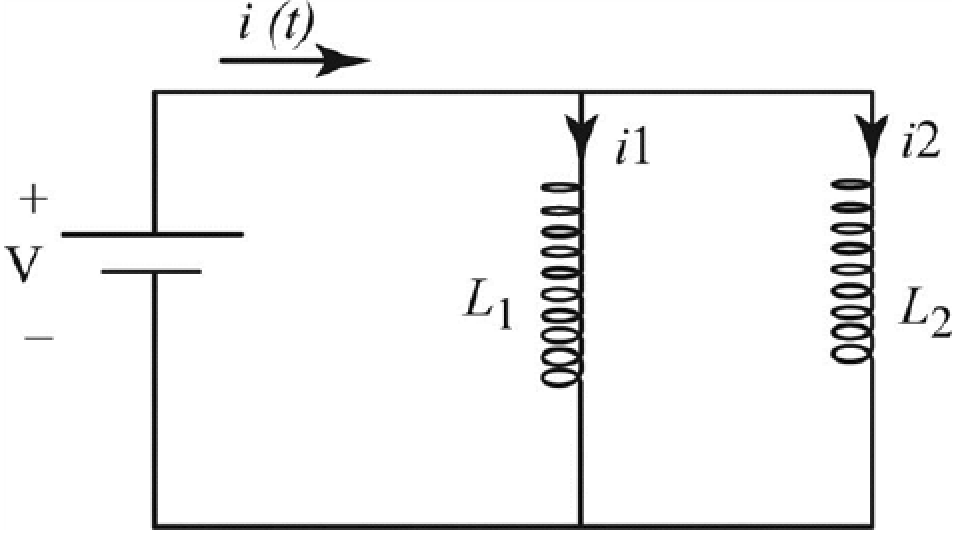
The flow of current in the circuit is as shown in the figure below.

Figure-(1)
Here,
Write the expression based on junction rule.
Here,
Write the expression to obtain the loop rule.
Here,
Write the expression based on junction rule to obtain the current division in the circuit.
Here,
Differentiate the above equation with respect to time
Write the expression based on loop rule to obtain the potential drop in the left loop.
Write the expression based on loop rule to obtain the potential drop in the right loop.
As the inductor
Compare equation (III) and (IV).
Further solve the above equation.
Substitute
Write the expression to obtain the voltage across the circuit.
Here,
Substitute
Further substitute
Compare equation (V) and (VI).
Further solve the above equation.
Therefore, the equivalent inductance for the system is
Want to see more full solutions like this?
Chapter 32 Solutions
Bundle: Physics for Scientists and Engineers with Modern Physics, Loose-leaf Version, 9th + WebAssign Printed Access Card, Multi-Term
- Hi Expert in Physics, Could you please Rewrite thses random equations using good formula of mathematics and explain each Greek alphabet and their meaning in English? Best Regards, Yahyaarrow_forwardHi Expert, I have uploaded picture, could you please name the Greek alphabet and their name in English?arrow_forwardHi Expert in Physics, I have uploaded pictures with respect to some physics equations. Could please name all Greek alphabet and their English name?arrow_forward
- 81 SSM Figure 29-84 shows a cross section of an infinite conducting sheet carrying a current per unit x-length of 2; the current emerges perpendicularly out of the page. (a) Use the Biot-Savart law and symmetry to show that for all points B P P. BD P' Figure 29-84 Problem 81. x P above the sheet and all points P' below it, the magnetic field B is parallel to the sheet and directed as shown. (b) Use Ampere's law to prove that B = ½µλ at all points P and P'.arrow_forwardWhat All equations of Ountum physics?arrow_forwardPlease rewrite the rules of Quantum mechanics?arrow_forward
- Suppose there are two transformers between your house and the high-voltage transmission line that distributes the power. In addition, assume your house is the only one using electric power. At a substation the primary of a step-down transformer (turns ratio = 1:23) receives the voltage from the high-voltage transmission line. Because of your usage, a current of 51.1 mA exists in the primary of the transformer. The secondary is connected to the primary of another step-down transformer (turns ratio = 1:36) somewhere near your house, perhaps up on a telephone pole. The secondary of this transformer delivers a 240-V emf to your house. How much power is your house using? Remember that the current and voltage given in this problem are rms values.arrow_forwardThe human eye is most sensitive to light having a frequency of about 5.5 × 10¹⁴ Hz, which is in the yellow-green region of the electromagnetic spectrum. How many wavelengths of this light can fit across a distance of 2.2 cm?arrow_forwardA one-dimensional harmonic oscillator of mass m and angular frequency w is in a heat bath of temperature T. What is the root mean square of the displacement of the oscillator? (In the expressions below k is the Boltzmann constant.) Select one: ○ (KT/mw²)1/2 ○ (KT/mw²)-1/2 ○ kT/w O (KT/mw²) 1/2In(2)arrow_forward
- Two polarizers are placed on top of each other so that their transmission axes coincide. If unpolarized light falls on the system, the transmitted intensity is lo. What is the transmitted intensity if one of the polarizers is rotated by 30 degrees? Select one: ○ 10/4 ○ 0.866 lo ○ 310/4 01/2 10/2arrow_forwardBefore attempting this problem, review Conceptual Example 7. The intensity of the light that reaches the photocell in the drawing is 160 W/m², when 0 = 18°. What would be the intensity reaching the photocell if the analyzer were removed from the setup, everything else remaining the same? Light Photocell Polarizer Insert Analyzerarrow_forwardThe lifetime of a muon in its rest frame is 2.2 microseconds. What is the lifetime of the muon measured in the laboratory frame, where the muon's kinetic energy is 53 MeV? It is known that the rest energy of the muon is 106 MeV. Select one: O 4.4 microseconds O 6.6 microseconds O 3.3 microseconds O 1.1 microsecondsarrow_forward
 Physics for Scientists and Engineers: Foundations...PhysicsISBN:9781133939146Author:Katz, Debora M.Publisher:Cengage Learning
 Physics for Scientists and Engineers, Technology ...PhysicsISBN:9781305116399Author:Raymond A. Serway, John W. JewettPublisher:Cengage Learning
 Physics for Scientists and EngineersPhysicsISBN:9781337553278Author:Raymond A. Serway, John W. JewettPublisher:Cengage Learning
 Physics for Scientists and Engineers with Modern ...PhysicsISBN:9781337553292Author:Raymond A. Serway, John W. JewettPublisher:Cengage Learning
 Principles of Physics: A Calculus-Based TextPhysicsISBN:9781133104261Author:Raymond A. Serway, John W. JewettPublisher:Cengage Learning


