
Vector Mechanics for Engineers: Statics
12th Edition
ISBN: 9781259977244
Author: BEER
Publisher: MCG
expand_more
expand_more
format_list_bulleted
Videos
Textbook Question
Chapter 3.2, Problem 3.59P
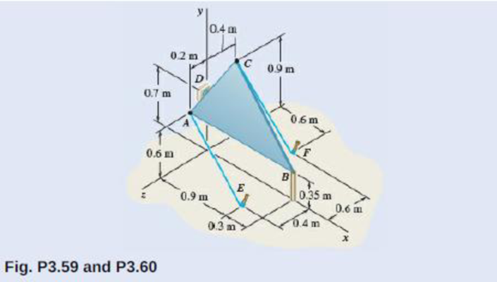
The triangular plate ABC is supported by ball-and-socket joints at B and D and is held in the position shown by cables AE and CF. If the force exerted by cable AE at A is 55 N, determine the moment of that force about the line joining points D and B.
Expert Solution & Answer
Want to see the full answer?
Check out a sample textbook solution
Students have asked these similar questions
mylabmastering.pearson.com
Chapter 12 - Lecture Notes.pptx: (MAE 272-01) (SP25) DY...
Document Sharing
P Pearson MyLab and Mastering
User Settings
Part A
P
Course Home
b Success Confirmation of Question Submission | bartleby
A particle moves along an Archimedean spiral
r = (80) ft, where 0 is given in radians. (Figure 1)
If ė = = 4 rad/s and € = 5 rad/s², determine the radial component of the particle's velocity at the instant
Express your answer to three significant figures and include the appropriate units.
Figure
y
r =
Α
?
Vr =
Value
Units
Submit
Request Answer
Part B
Determine the transverse component of the particle's velocity.
Express your answer to three significant figures and include the appropriate units.
о
MÅ
ve =
Value
Submit
Request Answer
Part C
Units
?
1 of 1
Determine the radial component of the particle's acceleration.
Express your answer to three significant figures and include the appropriate units.
Ar =
(80) ft
о
ΜΑ
Value
Units
?
= π/2 rad.
Can you help me with a matlab code? I am trying to plot the keplerian orbital elements over time. I would usually find the orbit using cartesian system and then transform into keplerian orbital elements. Is there a way to directly integrate keplerian orbital elements?
mylabmastering.pearson.com
Chapter 12 - Lecture Notes.pptx: (MAE 272-01) (SP25) DY...
P Pearson MyLab and Mastering
Scores
Chapter 3 Solutions
Vector Mechanics for Engineers: Statics
Ch. 3.1 - A foot valve for a pneumatic system is hinged at...Ch. 3.1 - 3.2A foot valve for a pneumatic system is hinged...Ch. 3.1 - It is known that a vertical force of 200 lb is...Ch. 3.1 - A 300-N force is applied at A as shown. Determine...Ch. 3.1 - A 300-N force is applied at A as shown. Determine...Ch. 3.1 - An 8-lb force P is applied to a shift lever....Ch. 3.1 - Prob. 3.7PCh. 3.1 - An 11-lb force P is applied to a shift lever. The...Ch. 3.1 - Rod AB is held in place by the cord AC. Knowing...Ch. 3.1 - Rod AB is held in place by the cord AC. Knowing...
Ch. 3.1 - 3.11 and 3.12The tailgate of a car is supported by...Ch. 3.1 - 3.11 and 3.12The tailgate of a car is supported by...Ch. 3.1 - 3.13 and 3.14It is known that the connecting rod...Ch. 3.1 - 3.13 and 3.14It is known that the connecting rod...Ch. 3.1 - Form the vector product P1 P2 and use the result...Ch. 3.1 - The vectors P and Q are two adjacent sides of a...Ch. 3.1 - Prob. 3.17PCh. 3.1 - Prob. 3.18PCh. 3.1 - Prob. 3.19PCh. 3.1 - Prob. 3.20PCh. 3.1 - Before the trunk of a large tree is felled, cables...Ch. 3.1 - The 12-ft boom AB has a fixed end A. A steel cable...Ch. 3.1 - A 200-N force is applied as shown to the bracket...Ch. 3.1 - A force P of magnitude 200 N acts along the...Ch. 3.1 - A 6-ft-long fishing rod AB is securely anchored in...Ch. 3.1 - A precast concrete wall section is temporarily...Ch. 3.1 - In Prob. 3.22, determine the perpendicular...Ch. 3.1 - In Prob. 3.23, determine the perpendicular...Ch. 3.1 - In Prob. 3.24, determine the perpendicular...Ch. 3.1 - In Prob. 3.25, determine the perpendicular...Ch. 3.1 - In Prob. 3.25, determine the perpendicular...Ch. 3.1 - In Prob. 3.26, determine the perpendicular...Ch. 3.1 - In Prob. 3.26, determine the perpendicular...Ch. 3.1 - Determine the value of a that minimizes the...Ch. 3.2 - Given the vectors P = 2i + j + 2k, Q = 3i + 4j ...Ch. 3.2 - Form the scalar product B C and use the result...Ch. 3.2 - Three cables are attached to the top of the tower...Ch. 3.2 - Prob. 3.38PCh. 3.2 - Knowing that the tension in cable AC is 280 lb,...Ch. 3.2 - Knowing that the tension in cable AD is 180 lb,...Ch. 3.2 - Ropes AB and BC are two of the ropes used to...Ch. 3.2 - Ropes AB and BC are two of the ropes used to...Ch. 3.2 - The 20-in. tube AB can slide along a horizontal...Ch. 3.2 - Solve Prob. 3.43 for the position corresponding to...Ch. 3.2 - Determine the volume of the parallelepiped of Fig....Ch. 3.2 - Prob. 3.46PCh. 3.2 - A crane is oriented so that the end of the 25-m...Ch. 3.2 - 3.48The 25-m crane boom AO lies in the yz plane....Ch. 3.2 - To loosen a frozen valve, a force F with a...Ch. 3.2 - 3.50When a force F is applied to the handle of the...Ch. 3.2 - The 0.61 1.00-m lid ABCD of a storage bin is...Ch. 3.2 - Prob. 3.52PCh. 3.2 - A farmer uses cables and winch pullers B and E to...Ch. 3.2 - Solve Prob. 3.53 when the tension in cable AB is...Ch. 3.2 - A force P of magnitude 520 lb acts on the frame...Ch. 3.2 - 3.56A force P acts on the frame shown at point E....Ch. 3.2 - The frame ACD is hinged at A and D and is...Ch. 3.2 - In Prob. 3.57, determine the moment about the...Ch. 3.2 - The triangular plate ABC is supported by...Ch. 3.2 - 3.60The triangular plate ABC is supported by...Ch. 3.2 - Prob. 3.61PCh. 3.2 - Prob. 3.62PCh. 3.2 - Two forces F1 and F2 in space have the same...Ch. 3.2 - Prob. 3.64PCh. 3.2 - Prob. 3.65PCh. 3.2 - In Prob. 3.57, determine the perpendicular...Ch. 3.2 - In Prob. 3.58, determine the perpendicular...Ch. 3.2 - In Prob. 3.59, determine the perpendicular...Ch. 3.2 - In Prob. 3.60, determine the perpendicular...Ch. 3.3 - Two 80-N forces are applied as shown to the...Ch. 3.3 - Two parallel 60-N forces are applied as shown to...Ch. 3.3 - A multiple-drilling machine is used to drill...Ch. 3.3 - Four pegs of the same diameter are attached to a...Ch. 3.3 - A piece of plywood in which several holes are...Ch. 3.3 - The shafts of an angle drive are acted upon by the...Ch. 3.3 - Prob. 3.76PCh. 3.3 - 3.77If P = 20 lb in the figure, replace the three...Ch. 3.3 - The two couples shown are to be replaced with a...Ch. 3.3 - Solve part a of Prob. 3.78, assuming that two 15-N...Ch. 3.3 - Shafts A and B connect the gear box to the wheel...Ch. 3.3 - A 500-N force is applied to a bent plate as shown....Ch. 3.3 - A crane column supports a 16-kip load as shown....Ch. 3.3 - A dirigible is tethered by a cable attached to its...Ch. 3.3 - A 30-lb vertical force P is applied at A to the...Ch. 3.3 - A worker tries to move a rock by applying a 360-N...Ch. 3.3 - A worker tries to move a rock by applying a 360-N...Ch. 3.3 - The shearing forces exerted on the cross section...Ch. 3.3 - Knowing that = 60, replace the force and couple...Ch. 3.3 - Three control rods attached to a lever ABC exert...Ch. 3.3 - A rectangular plate is acted upon by the force and...Ch. 3.3 - While tapping a hole, a machinist applies the...Ch. 3.3 - A hexagonal plate is acted upon by the force P and...Ch. 3.3 - Replace the 250-kN force P with an equivalent...Ch. 3.3 - A 2.6-kip force is applied at point D of the...Ch. 3.3 - Replace the 150-N force with an equivalent...Ch. 3.3 - To keep a door closed, a wooden stick is wedged...Ch. 3.3 - A 46-lb force F and a 2120-lbin. couple M are...Ch. 3.3 - A 110-N force acting in a vertical plane parallel...Ch. 3.3 - The 12-ft boom AB has a fixed end A, and the...Ch. 3.3 - The jib crane shown is oriented so that its boom...Ch. 3.4 - 3.101A 4-m-long beam is subjected to a variety of...Ch. 3.4 - Prob. 3.102PCh. 3.4 - Determine the single equivalent force and the...Ch. 3.4 - Five separate force-couple systems act at the...Ch. 3.4 - The weights of two children sitting at ends A and...Ch. 3.4 - Three stage lights are mounted on a pipe as shown....Ch. 3.4 - A beam supports three loads of given magnitude and...Ch. 3.4 - A 6 12-in. plate is subjected to four loads as...Ch. 3.4 - Gear C is rigidly attached to arm AB. If the...Ch. 3.4 - To test the strength of a 625 500-mm suitcase,...Ch. 3.4 - Two cables exert forces of 90 kN each on a truss...Ch. 3.4 - Pulleys A and B are mounted on bracket CDEF. The...Ch. 3.4 - The roof of a building frame is subjected to the...Ch. 3.4 - A couple of magnitude M = 80 lbin. and the three...Ch. 3.4 - A couple M and the three forces shown are applied...Ch. 3.4 - A machine component is subjected to the forces and...Ch. 3.4 - Solve Prob. 3.116, assuming that P = 60 N.Ch. 3.4 - As follower AB rolls along the surface of member...Ch. 3.4 - A machine component is subjected to the forces...Ch. 3.4 - Two 150-mm-diameter pulleys are mounted on line...Ch. 3.4 - As an adjustable brace BC is used to bring a wall...Ch. 3.4 - In order to unscrew the tapped faucet A, a plumber...Ch. 3.4 - Assuming = 60 in Prob. 3.122, replace the two...Ch. 3.4 - Four forces are applied to the machine component...Ch. 3.4 - A blade held in a brace is used to tighten a screw...Ch. 3.4 - A mechanic uses a crowfoot wrench to loosen a bolt...Ch. 3.4 - Prob. 3.127PCh. 3.4 - Prob. 3.128PCh. 3.4 - Four signs are mounted on a frame spanning a...Ch. 3.4 - Prob. 3.130PCh. 3.4 - A concrete foundation mat of 5-m radius supports...Ch. 3.4 - Determine the magnitude and the point of...Ch. 3.4 - Prob. 3.133PCh. 3.4 - A piece of sheet metal is bent into the shape...Ch. 3.4 - Prob. 3.135PCh. 3.4 - Prob. 3.136PCh. 3.4 - Two bolts at A and B are tightened by applying the...Ch. 3.4 - Two bolts at A and B are tightened by applying the...Ch. 3.4 - Prob. 3.139PCh. 3.4 - A flagpole is guyed by three cables. If the...Ch. 3.4 - 3.141 and 3.142Determine whether the...Ch. 3.4 - 3.141 and 3.142Determine whether the...Ch. 3.4 - Replace the wrench shown with an equivalent system...Ch. 3.4 - Show that, in general, a wrench can be replaced...Ch. 3.4 - Show that a wrench can be replaced with two...Ch. 3.4 - Show that a wrench can be replaced with two...Ch. 3 - A 300-N force P is applied at point A of the bell...Ch. 3 - A winch puller AB is used to straighten a fence...Ch. 3 - A small boat hangs from two davits, one of which...Ch. 3 - Prob. 3.150RPCh. 3 - A single force P acts at C in a direction...Ch. 3 - The 23-in. vertical rod CD is welded to the...Ch. 3 - In a manufacturing operation, three holes are...Ch. 3 - A 260-lb force is applied at A to the rolled-steel...Ch. 3 - Prob. 3.155RPCh. 3 - A 77-N force F1 and a 31-Nm couple M1 are applied...Ch. 3 - Three horizontal forces are applied as shown to a...Ch. 3 - While using a pencil sharpener, a student applies...
Knowledge Booster


Learn more about
Need a deep-dive on the concept behind this application? Look no further. Learn more about this topic, mechanical-engineering and related others by exploring similar questions and additional content below.Similar questions
- K mylabmastering.pearson.com Chapter 12 - Lecture Notes.pptx: (MAE 272-01) (SP25) DY... P Pearson MyLab and Mastering Mastering Engineering Back to my courses Course Home Scores Course Homearrow_forwardK mylabmastering.pearson.com Chapter 12 - Lecture Notes.pptx: (MAE 272-01) (SP25) DY... P Pearson MyLab and Mastering Mastering Engineering Back to my courses Course Home Scores Course Homearrow_forwardChapter 12 - Lecture Notes.pptx: (MAE 272-01) (SP25) DY... Scoresarrow_forwardIn a single cylinder, four stroke, single acting gas engine, the cylinder diameter is 180 mm and the stroke is 350 mm . When running at 250 rpm , the mean area of the indicator diagram taken off the engine is 355 mm² , length of diagram 75 mm , scale of the indicator spring 90 kN/m sq per mm , and the number of explosions was counted to be 114 per minute. Calculate the indicated power. so i have already asked this question and got a good answer, however on step 4, i dont understand how they reached 18.43 KW. When i do the math provided, i get the answer 7195.566. Where am i going wrong? thanks StepsTo clarify how we determined the Indicated Power, I'll go over each step in detail. Step 1: Comprehending the Provided Information - Cylinder diameter (in meters) = 180 mm = 0.18 m - Stroke length (in meters) = 350 mm = 0.35 m - Engine speed = 250 rpm -Indicator diagram mean area = 355 mm² The diagram's length is 75 mm; its spring scale is 90 kN/m² per mm, or 90,000 N/m² per mm; and…arrow_forwardIn MATLAB, can you help me simulate an orbit under earth J2 perturbation with the Milankovich orbital elements? Also, can you check to see if they fit the Milankovich constraint equaiton?arrow_forward8. All of the members in the Warren truss of Figure 8 are of length 10 ft. Use the method of sections to determine the forces in the members BD,CD,CE. B A C D E F G 2000 lb 3000 lb 5000 lb Figure 8 Harrow_forwardAn acrobat is walking on a tightrope of length L =20.1 m attached to supports A and B at a distance of 20.0 m apart. The combined weight of the acrobat and his balancing pole is 900 N, and the friction between his shoes and the rope is large enough to prevent him from slipping. Neglecting the weight of the rope and any elastic deformation, determine the deflection (y) and the tension in portion AC and BC of the rope for values of x from 0.5 m to 10 m using 0.5 m increments. 1. Determine the maximum deflection (y) in the rope. 2. Plot tension of AC and BC vs. x (on the same plot with x on the x-axis). Turn in the plot and the table of x, TAC, and TBC (clearly label each). A C 20.0 m Barrow_forward5. A 4000 lb block of concrete is attached by light inextensible cables to the truss in Figure 5. Determine the force in each member. State whether each member is in tension or compression. 3 ΘΑ D E cables all dimensions in feet.arrow_forwardA block hangs from the end of bar AB that is 5.80 meters long and connected to the wall in the xz plane. The bar is supported at end A by a ball joint such that it carries only a compressive force along its axis. The bar is supported in equilibrium at end B by cables BD and BC that connect to the xz plane at points C and D respectively with coordinates given in the figure. The z components of the moments exerted on the bar by these two cables sum to 0. The tension in cable BD is measured to be 210 Newtons. Input answers of zero as 0.00 to avoid an invalid answer due to significant figures. Determine the equivalent force and couple system acting at A that models only the forces exerted by both cables BD → and BC on the bar at B. Enter your results for Feq and Meg in Cartesian Components. Z D (c, 0, d) C (a, 0, b). X A f m B y cc 040 BY NC SA 2016 Eric Davishahl Values for dimensions on the figure are given in the following table. Note the figure may not be to scale. Variable Value a…arrow_forwardA bent tube is attached to a wall with brackets as shown. A force of F = 785 lb is applied to the end of the tube with direction indicated by the dimensions in the figure. a.) Determine the moment about point D due to the force F Enter your answer in Cartesian components with units of ft- lbs. b.) Determine the moment about a line (i.e. axis) running from D to C due to the force F. Enter your answer in Cartesian components with units of ft-lbs. 2013 Michael Swanbom x BY NC SA g Z h A с FK kaz Values for dimensions on the figure are given in the table below. Note the figure may not be to scale. Be sure to align your cartesian unit vectors with the coordinate axes shown in the figure. Variable Value α 4.84 in b 13.2 in с 12.5 in d 30.8 in h 18.7 in 22.0 in →> a. MD=( i+ k) ft- lb →> b. MDC = î + k) ft- lbarrow_forwardF1 3 4 5 P F2 F2 Ꮎ e b 200 3 4 5 F1 The electric pole is subject to the forces shown. Force F1 245 N and force F2 = 310 N with an angle 0 = 20.2°. Determine the moment about point P of all forces. Take counterclockwise moments to be positive. = Values for dimensions on the figure are given in the following table. Note the figure may not be to scale. Variable Value a 2.50 m b 11.3 m с 13.0 m The moment about point P is m. N- If the moment about point P sums up to be zero. Determine the distance c while all other values remained the same. m.arrow_forwardF y b C 10 Z Determine the moment about O due to the force F shown, the magnitude of the force F = 76.0 lbs. Note: Pay attention to the axis. Values for dimensions on the figure are given in the following table. Note the figure may not be to scale. Variable Value a 1.90 ft b 2.80 ft с 2.60 ft d 2.30 ft Mo = lb + k) ft-arrow_forwardarrow_back_iosSEE MORE QUESTIONSarrow_forward_ios
Recommended textbooks for you
 International Edition---engineering Mechanics: St...Mechanical EngineeringISBN:9781305501607Author:Andrew Pytel And Jaan KiusalaasPublisher:CENGAGE L
International Edition---engineering Mechanics: St...
Mechanical Engineering
ISBN:9781305501607
Author:Andrew Pytel And Jaan Kiusalaas
Publisher:CENGAGE L
How to balance a see saw using moments example problem; Author: Engineer4Free;https://www.youtube.com/watch?v=d7tX37j-iHU;License: Standard Youtube License