
Videos
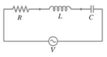
(II) In the LRC circuit or Fig. 30–19, suppose I = I0 sin ωt and V − V0 sin(ωt + ϕ). Determine the instantaneous power dissipated in the circuit from P = IV using these equations and show that on the average,
FIGURE 30-19 An LRC circuit.
We multiply the instantaneous current by the instantaneous voltage to calculate the instantaneous power. Then using the trigonometric identity for the summation of sine arguments (inside back cover of text) we can simplify the result. We integrate the power over a full period and divide the result by the period to calculate the average power.
P = IV = (I0 sin ωt)V0 sin(ωt + ϕ) = I0V0 sin ωt cosϕ +sinϕ cos ωt)
= I0V0 (sin2 ωt cosϕ +sin ωt cos ωt sinϕ
Want to see the full answer?
Check out a sample textbook solution
Chapter 30 Solutions
Physics for Scientists and Engineers with Modern Physics
Additional Science Textbook Solutions
Conceptual Physical Science (6th Edition)
The Cosmic Perspective (8th Edition)
University Physics Volume 1
The Cosmic Perspective
Essential University Physics: Volume 1 (3rd Edition)
Conceptual Integrated Science


- Calculate volt in the given circuit, where R= 22 Q. 50 Ω 50 μF 60 sin 200f V 0.1 H ,(t) The value of vol) is |cos(200t) V.arrow_forward() THE FOLLOWING QUESTIONS ARE BASED ON THE INFORMATION GIVEN HERE. R C In the circuit shown in the figure, the S switch is closed at R t = 0 and the capacitors, which are completely empty, begin to ww fill. Here E = 25 V, C = 7 µF and R = 20 2. A) What is the time constant of the circuit, T, in units of microseconds? Answer: B) When t = T, what is the total charge, in units of microcoulomb, accumulated in the capacitors? Answer:arrow_forwardIn the circuit ɛ =4.6 kV, C = 7.9µF, R, = R2 = R3 = 0.74 MQ. With C completely uncharged, switch S is suddenly closed at t=0, a) at t=0 find the current in all resistors b) Fint the current in all resistors at t=, c) potential difference across resesitor 2 at t=0 and t=∞ R Rg Ro ww-arrow_forward
- (d) an extension cord having a 0.065 resistance and through which 4 A is flowing: P= W (e) a cheaper cord utilizing thinner wire and with a resistance of 0.15 2.; P= W (f) Which extension cord dissipates more power? O The more expensive thicker power cord O The cheaper thinner power cordarrow_forward() THE FOLLOWING QUESTIONS ARE BASED ON THE INFORMATION GIVEN HERE. R ww C In the circuit shown in the figure, the S switch is closed at t = 0 and the capacitors, which are completely empty, begin to fill. Here E = 50 V, C = 4 µF and R = 15 N. R ww A) What is the time constant of the circuit, T, in units of microseconds? Yanıt: B) When t = T, what is the total charge, in units of microcoulomb, accumulated in the capacitors?arrow_forward59 In Fig. 27-51, R₁ = 20.0 2, R₂ = 10.0 2, and the ideal bat- tery has emf & = 120 V. What is the current at point a if we close (a) only switch S₁, (b) only switches S₁ and S₂, and (c) all three switches? Figure 27-51 Problem 59. a S₁ S₂ S3 18 R₁ R₁ R₁ I'm LwIw Im R₁ R₂ R₂arrow_forward
- (a) In the figure what value must R have if the current in the circuit is to be 1.3 mA? Take ₁ = 2.7 V, 8₂ = 5.3 V, and r₁= r₂ = 3.9 Q. (b) What is the rate at which thermal energy appears in R? ww www. (b) Number 12₂ (a) Number 1992.2 i 2.6 Units Units Ω W <arrow_forward(e) In the circuit shown in Figure 2, the supply voltage Vs= 5V Dc, R1 = 100, R2 = 560 and R3 = 390. Is R1 12 Vs R2 R3 Figure 2 (i) Identify the number of loops and branches in the circuit. (ii) Calculate the supply current Is. (iii) What is the required power rating of resistor R1? (iv) What is the voltage drop across resistor R2?arrow_forward(II) A power station delivers 750 kW of power at 12,000 Vto a factory through wires with total resistance 3.0 Ω Howmuch less power is wasted if the electricity is delivered at50,000 V rather than 12,000 V?arrow_forward
- **57 Go In Fig. 30-63, R = 15 N, L = 5.0 H, the ideal battery has & = 10 V, and the fuse in the upper branch is an ideal 3.0 A fuse. It has Fuse R zero resistance as long as the cur- rent through it remains less than 3.0 L. A. If the current reaches 3.0 A, the fuse “blows" and thereafter has in- finite resistance. Switch S is closed Fig. 30-63 Problem 57. at time t= 0. (a) When does the fuse blow? (Hint: Equation 30-41 does not apply. Rethink Eq. 30-39.) (b) Sketch a graph of the current i through the inductor as a function of time. Mark the time at which the fuse blows.arrow_forwardSubject:- physicsarrow_forward7 Figure 30-27 shows a circuit with two identical resistors and an ideal in- ductor. Is the current through the cen- tral resistor more than, less than, or the same as that through the other resistor (a) just after the closing of switch S, (b) a long time after that, (c) just after S is reopened a long time later, and (d) a long time after that? Figure 30-26 Question 6.arrow_forward

 Glencoe Physics: Principles and Problems, Student...PhysicsISBN:9780078807213Author:Paul W. ZitzewitzPublisher:Glencoe/McGraw-Hill
 Physics for Scientists and EngineersPhysicsISBN:9781337553278Author:Raymond A. Serway, John W. JewettPublisher:Cengage Learning
 Physics for Scientists and Engineers with Modern ...PhysicsISBN:9781337553292Author:Raymond A. Serway, John W. JewettPublisher:Cengage Learning
 Physics for Scientists and Engineers: Foundations...PhysicsISBN:9781133939146Author:Katz, Debora M.Publisher:Cengage Learning
 Principles of Physics: A Calculus-Based TextPhysicsISBN:9781133104261Author:Raymond A. Serway, John W. JewettPublisher:Cengage Learning