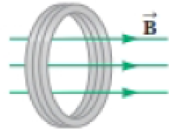
Figure P30.41 shows a compact, circular coil with 220 turns and radius 12.0 cm immersed in a uniform magnetic field parallel to the axis of the coil. The rate of change of the field has the constant magnitude 20.0 mT/s. (a) What additional information is necessary to determine whether the coil is carrying clockwise or counterclockwise current? (b) The coil overheats if more than 160 W of power is delivered to it. What resistance would the coil have at this critical point? (c) To run cooler, should it have lower resistance or higher resistance?
Figure P30.41

Trending nowThis is a popular solution!

Chapter 30 Solutions
Bundle: Physics For Scientists And Engineers With Modern Physics, Loose-leaf Version, 10th + Webassign Printed Access Card For Serway/jewett's Physics For Scientists And Engineers, 10th, Single-term
Additional Science Textbook Solutions
Applications and Investigations in Earth Science (9th Edition)
Laboratory Experiments in Microbiology (12th Edition) (What's New in Microbiology)
Organic Chemistry
Fundamentals Of Thermodynamics
Introductory Chemistry (6th Edition)
- No chatgpt pls will upvotearrow_forward1.62 On a training flight, a Figure P1.62 student pilot flies from Lincoln, Nebraska, to Clarinda, Iowa, next to St. Joseph, Missouri, and then to Manhattan, Kansas (Fig. P1.62). The directions are shown relative to north: 0° is north, 90° is east, 180° is south, and 270° is west. Use the method of components to find (a) the distance she has to fly from Manhattan to get back to Lincoln, and (b) the direction (relative to north) she must fly to get there. Illustrate your solutions with a vector diagram. IOWA 147 km Lincoln 85° Clarinda 106 km 167° St. Joseph NEBRASKA Manhattan 166 km 235° S KANSAS MISSOURIarrow_forwardPlz no chatgpt pls will upvotearrow_forward
- 3.19 • Win the Prize. In a carnival booth, you can win a stuffed gi- raffe if you toss a quarter into a small dish. The dish is on a shelf above the point where the quarter leaves your hand and is a horizontal dis- tance of 2.1 m from this point (Fig. E3.19). If you toss the coin with a velocity of 6.4 m/s at an angle of 60° above the horizontal, the coin will land in the dish. Ignore air resistance. (a) What is the height of the shelf above the point where the quarter leaves your hand? (b) What is the vertical component of the velocity of the quarter just before it lands in the dish? Figure E3.19 6.4 m/s 2.1arrow_forwardCan someone help me answer this thank you.arrow_forward1.21 A postal employee drives a delivery truck along the route shown in Fig. E1.21. Determine the magnitude and direction of the resultant displacement by drawing a scale diagram. (See also Exercise 1.28 for a different approach.) Figure E1.21 START 2.6 km 4.0 km 3.1 km STOParrow_forward
- help because i am so lost and it should look something like the picturearrow_forward3.31 A Ferris wheel with radius Figure E3.31 14.0 m is turning about a horizontal axis through its center (Fig. E3.31). The linear speed of a passenger on the rim is constant and equal to 6.00 m/s. What are the magnitude and direction of the passenger's acceleration as she passes through (a) the lowest point in her circular motion and (b) the high- est point in her circular motion? (c) How much time does it take the Ferris wheel to make one revolution?arrow_forward1.56 ⚫. Three horizontal ropes pull on a large stone stuck in the ground, producing the vector forces A, B, and C shown in Fig. P1.56. Find the magnitude and direction of a fourth force on the stone that will make the vector sum of the four forces zero. Figure P1.56 B(80.0 N) 30.0 A (100.0 N) 53.0° C (40.0 N) 30.0°arrow_forward
 Physics for Scientists and EngineersPhysicsISBN:9781337553278Author:Raymond A. Serway, John W. JewettPublisher:Cengage Learning
 Physics for Scientists and Engineers with Modern ...PhysicsISBN:9781337553292Author:Raymond A. Serway, John W. JewettPublisher:Cengage Learning
 Glencoe Physics: Principles and Problems, Student...PhysicsISBN:9780078807213Author:Paul W. ZitzewitzPublisher:Glencoe/McGraw-Hill
 Principles of Physics: A Calculus-Based TextPhysicsISBN:9781133104261Author:Raymond A. Serway, John W. JewettPublisher:Cengage Learning
 Physics for Scientists and Engineers: Foundations...PhysicsISBN:9781133939146Author:Katz, Debora M.Publisher:Cengage Learning


