
Videos
(a)
The magnitude and direction of the resultant velocity vector
Answer to Problem 39QAP
The resultant velocity vector
Explanation of Solution
Given:
The magnitude and the directions of the velocity vectors
Formula used:
If
The magnitude of the vector
The angle the vector makes with the x axis is given by,
Calculation:
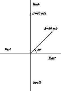
Assume the +x axis to be directed along the East and the +yaxis along the North.
Draw a vector diagram for the velocities.
The vector
The velocity vector
Calculate the x and y components of the vector
Calculate the magnitude of the resultant velocity vector
Calculate the angle made by the vector with the +x axis (East).
Conclusion:
The resultant velocity vector
(b)
The magnitude and direction of the resultant velocity vector
Answer to Problem 39QAP
The resultant velocity vector
Explanation of Solution
Given:
From part (a), the components of the vectors
Formula used:
If
The magnitude of the vector
The angle made by the vector with the x axis is given by,
Calculation:
Calculate the x and y components of the vector
Calculate the magnitude of the vector
Calculate the angle made by the vector
Since the y component of
Conclusion:
The resultant velocity vector
(c)
The magnitude and the direction of the resultant velocity vector
Answer to Problem 39QAP
The resultant velocity vector
Explanation of Solution
Given:
From part (a), the components of the vectors
Formula used:
If
The magnitude of the vector
The angle made by the vector with the x axis is given by,
Calculation:
Calculate the x and y components of the vector
Calculate the magnitude of the vector
Calculate the angle made by the vector
Conclusion:
The resultant velocity vector
Want to see more full solutions like this?
Chapter 3 Solutions
COLLEGE PHYSICS LL W/ 6 MONTH ACCESS


- If a 120- volt circuit feeds four 40-watt fluorescent lamps, what current (in amps) is drawn if the power factor is 0.912 0.33 0.68 1.21 3.3arrow_forwardHow do you draw a diagram of the ruler and mass system in equilibrium identifying the anti-clockwise torque and clockwise torque? How do I calculate the anti-clockwise torque and the clockwise torque of the system with the ruler and the washers, does it come from the data in table 2? Please help, thank you!arrow_forwardA long, narrow steel rod of length 2.5000 m at 33.5°C is oscillating as a pendulum about a horizontal axis through one end. If the temperature drops to 0°C, what will be the fractional change in its period?arrow_forward
- How long should a pendulum be in order to swing back and forth in 1.6 s?arrow_forwardLECTURE HANDOUT: REFRACTION OF LIGHT I. Review Each of the diagrams at right shows a ray incident on a boundary between two media. Continue each of the rays into the second medium. Using a dashed line, also draw the path that the wave would have taken if it had continued without "bending." Does the ray representing a wave "bend" toward or away from the normal when: the wave speed is smaller in the second medium? ⚫the wave speed is larger in the second medium? Faster medium Slower medium Slower medium Faster medium II. Qualitative applications of refraction A. Place a coin at the bottom of an empty can or cup. Look into the cup at the coin while your partner slowly moves the can away from you until you no longer see the coin. Now, keep your head steady while your partner gently pours water into the cup. 1. Describe your observations. Switch roles with your partner so that you each have a turn. Shown below are cross-sectional diagrams of the cup for when it was empty and when it was…arrow_forwardProblem Six. A 70 kg student in the figure balances a 1200 kg elephant on a hydraulic lift with diameter 2.0 m that is filled with oil which has a density of 900 kg/m³. How many 80 kg students would have to stand on the first piston in order to raise the elephant by 2.55 m? 80 kg 1200 kg 17.) (A) 5 (D) 8 (B) 6 (E) 9 (C) 7 Oil 2.0 m 5arrow_forward
- In the accompanying figure, the rails, connecting end pieces, and rod all have a resistance per unit length of 4.52/cm. The rod moves to the left at v = 5 m/s. If B = 0.3 T everywhere in the region, what is the current in the circuit (a) when a = 6.5 cm? (b) when a = 4 cm?arrow_forwardProblem Twelve. An object consists of four particles: m₁ =1.0kg, m₂ = 2.0kg, m3 = 3.0kg, ma = 4.0kg. They are connected by rigid massless rods to form a rectangle of edge lengths 2a and 2b, where a 7.0 m and b = 8.0 m. The system rotates about the x-axis through the center as shown. = Find the (x, y) coordinate of the center of gravity of the object (in meters). Use the geometrical center of the object as the origin. 2a 13 2b m M2 Axis of rotation 20.) (A) (-3.2, -1.4) (B) (-3.2, 1.4) (C) (5.2, -1.4) (D) (-1.8,-1.4) (E) (3.2,-5.2) Find the moment of inertia of the object about the x-axis and y-axis that run through the geometrical center of the object. Give an answer as (Ix, ly, I) in units of 10² kg-m². 21.) (A) (6.4, 4.9, 11) (D) (9.8, 11, 12.8) (B) (4.9, 6.4, 11) (C) (11, 12.8, 9.8) (E) (2.5, 10, 11) anul babogaus al bos ano 002 maldor If the object is spinning with angular velocity of 30 rpm around the axis of rotation shown in the diagram, find the rotational kinetic energy. Give…arrow_forwardProblem Eleven. A hollow sphere with rotational inertia 1 = (2/3)MR2 is moving with speed v down an incline of angle 0 toward a spring with spring constant k. After traveling a distance d down the incline with no slipping, the sphere makes contact with the spring and compresses it a distance x before it comes momentarily to rest. Find the distance d in terms of the other quantities given. (21) 19.) (A) d=- 2Mg sin kx²-Mv² +x (B) d= 2Mg sin kx²+Mv² +x kx²-Mv² (C) d=- -x (D) d= 2Mg sin 2Mg cos kx²-Mv² 2Mg sin -x (E) d= kx²-Mv²arrow_forward
- 1. A light bulb operates at a temperature of 4,300 K and has an emissivity of 0.600 and a surface area of 5.50 mm². How long would the light bulb have to shine on a 2.00 g piece of ice that is at -30.0°C in order to turn the ice into steam at 120°C? Assume all the energy radiated by the light bulb is absorbed by the ice while it becomes liquid and eventually steam. Give an answer in seconds. The following are specific heats for ice, water, and steam. Cice = 2,090 ***C kg kg."C Cwater = 4,186 C Csteam = 2,010 C kg"C The following are latent heats for water. L 3.33 x 10' J/kg Lv = 2.26 x 10° J/kg (A) 31.6 (B) 56.9 (C) 63.5 (D) 21.6 (E) 97.4 Suppose q; consists of three protons and 92 consists of two protons. Let q; be at the origin and q2 be located at d along the x-axis. See the diagram below. 91 92 Χ d 2. Where would the net electric potential due to these two charges be zero? (A) to the left of gi (B) to the right of 92 (D) to the right of 92, as well as to the left of gi (E) Between…arrow_forwardProblem Six: A homogeneous solid object floats in water with 60.0% of its volume below the surface. When placed in a second liquid, the same object floats with 90.0% of its volume below the surface. (The density of water is 1,000 kg/m³.) Determine the density of the object in kg/m³. 19.) (A) 430 (B) 280 Determine the specific gravity of the liquid. 20.) (A) 0.331 (B) 0.760 (C) 560 (D) 600 (E) 720 (C) 0.880 (D) 0.280 (E) 0.667arrow_forwardA 1000-kg car traveling east at 30.0 m/s collides with a 950-kg car traveling north at 25.0 m/s. The cars stick together. Assume that any other unbalanced forces are negligible. What is the speed of the wreckage just after the collision? Please do on paper and show all equations and work done to get to the final answer. Along with any helpful diagrams if needed. These are a part of my review questions in the book but i keep getting different answers from what the book says, it is not a graded assignment***arrow_forward
 College PhysicsPhysicsISBN:9781938168000Author:Paul Peter Urone, Roger HinrichsPublisher:OpenStax College
 Principles of Physics: A Calculus-Based TextPhysicsISBN:9781133104261Author:Raymond A. Serway, John W. JewettPublisher:Cengage Learning
 College PhysicsPhysicsISBN:9781305952300Author:Raymond A. Serway, Chris VuillePublisher:Cengage Learning
 Physics for Scientists and Engineers, Technology ...PhysicsISBN:9781305116399Author:Raymond A. Serway, John W. JewettPublisher:Cengage Learning
 Physics for Scientists and Engineers with Modern ...PhysicsISBN:9781337553292Author:Raymond A. Serway, John W. JewettPublisher:Cengage Learning
 College PhysicsPhysicsISBN:9781285737027Author:Raymond A. Serway, Chris VuillePublisher:Cengage Learning