
Concept explainers
Videos
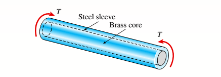
The composite shaft shown in the figure is manufactured by shrink-Fitting a steel sleeve over a brass core so that the two parts act as a single solid bar in torsion. The outer diameters of the two parts are dY= 40 mm for the brass core and d2= 50 mm for the steel sleeve. The shear moduli of elasticity are Gb= 36 GPa for the brass and Gs= 80 GPa for the steel.
(a)
Assuming that the allowable shear stresses
in the brass and steel are rb= 48 MPa and
ts= 80 MPa, respectively, determine the maximum permissible torque Tmax that may be applied to the shaft.
(b)
If the applied torque T = 2500 kN · m, find
the required diameter d2so that allowable shear
stress t3is reached in the steel.

(a)
The maximum permissible torque applied to the shaft.
Answer to Problem 3.8.14P
The maximum permissible torque applied to the shaft is
Explanation of Solution
Given information:
The outer diameter of steel sleeve is
Write the expression for total torque of the system.
Here, the total torque in the system is
Write the expression for polar moment of inertia of the brass core.
Here, the polar moment of inertia of brass core is
Write the expression for polar moment of inertia of steel sleeve.
Here, the polar moment of inertia of steel sleeve is
Write the expression for torque on the brass core
Here, the torque in the bar is
Write the expression for torque in the steel sleeve.
Here, the torque in the bar is
Write the expression for maximum shear stress in brass core.
Here, the maximum shear stress in the brass core is
Write the expression for maximum shear stress in the steel sleeve.
Here, the maximum shear stress in the bar is
Calculation:
Substitute
Substitute
Substitute
Substitute
Substitute
Substitute
Conclusion:
The maximum permissible torque applied to the shaft is
(b)
The diameter of the steel sleeve.
Answer to Problem 3.8.14P
The diameter of the steel sleeve is
Explanation of Solution
Given information:
The applied torque is
Substitute,
Substitute
Calculation:
Substitute
Conclusion:
The diameter of the steel sleeve is
Want to see more full solutions like this?
Chapter 3 Solutions
Mechanics of Materials, SI Edition


- An unpressurized cylindrical tank with a 100-foot diameter holds a 40-foot column of water. What is total force acting against the bottom of the tank?arrow_forward7. In the following problems check to see if the set S is a vector subspace of the corresponding R. If it is not, explain why not. If it is, then find a basis and the dimension. (a) S = (b) S = {[],+,"} X1 x12x2 = x3 CR³ {[1], 4+4 = 1} CR³ X2arrow_forwardAAA Show laplace transform on 1; (+) to L (y(+)) : SY(s) = x (0) Y(s) = £ [lx (+)] = 5 x(+) · est de 2 -St L [ y (^) ] = So KG) et de D 2 D D AA Y(A) → Y(s) Ŷ (+) → s Y(s) -yarrow_forward
- 1) In each of the following scenarios, based on the plane of impact (shown with an (n, t)) and the motion of mass 1, draw the direction of motion of mass 2 after the impact. Note that in all scenarios, mass 2 is initially at rest. What can you say about the nature of the motion of mass 2 regardless of the scenario? m1 15 <+ m2 2) y "L χ m1 m2 m1 בז m2 Farrow_forward8. In the following check to see if the set S is a vector subspace of the corresponding Rn. If it is not, explain why not. If it is, then find a basis and the dimension. X1 (a) S = X2 {[2], n ≤ n } c X1 X2 CR² X1 (b) S X2 = X3 X4 x1 + x2 x3 = 0arrow_forward2) Suppose that two unequal masses m₁ and m₂ are moving with initial velocities V₁ and V₂, respectively. The masses hit each other and have a coefficient of restitution e. After the impact, mass 1 and 2 head to their respective gaps at angles a and ẞ, respectively. Derive expressions for each of the angles in terms of the initial velocities and the coefficient of restitution. m1 m2 8 m1 ↑ บา m2 ñ Вarrow_forward
- The fallowing question is from a reeds book on applied heat i am studying. Although the answer is provided, im struggling to understand the whole answer and the formulas and the steps theyre using. Also where some ov the values such as Hg and Hf come from in part i for example. Please explain step per step in detail thanks In an NH, refrigerator, the ammonia leaves the evaporatorand enters the cornpressor as dry saturated vapour at 2.68 bar,it leaves the compressor and enters the condenser at 8.57 bar with50" of superheat. it is condensed at constant pressure and leavesthe condenser as saturated liquid. If the rate of flow of the refrigerantthrough the circuit is 0.45 kglmin calculate (i) the compressorpower, (ii) the heat rejected to the condenser cooling water in kJ/s,an (iii) the refrigerating effect in kJ/s. From tables page 12, NH,:2.68 bar, hg= 1430.58.57 bar, hf = 275.1 h supht 50" = 1597.2Mass flow of refrigerant--- - - 0.0075 kgls 60Enthalpy gain per kg of refrigerant in…arrow_forwardstate the formulas for calculating work done by gasarrow_forwardExercises Find the solution of the following Differential Equations 1) y" + y = 3x² 3) "+2y+3y=27x 5) y"+y=6sin(x) 7) y"+4y+4y = 18 cosh(x) 9) (4)-5y"+4y = 10 cos(x) 11) y"+y=x²+x 13) y"-2y+y=e* 15) y+2y"-y'-2y=1-4x³ 2) y"+2y' + y = x² 4) "+y=-30 sin(4x) 6) y"+4y+3y=sin(x)+2 cos(x) 8) y"-2y+2y= 2e* cos(x) 10) y+y-2y=3e* 12) y"-y=e* 14) y"+y+y=x+4x³ +12x² 16) y"-2y+2y=2e* cos(x)arrow_forward
- The state of stress at a point is σ = -4.00 kpsi, σy = 16.00 kpsi, σ = -14.00 kpsi, Try = 11.00 kpsi, Tyz = 8.000 kpsi, and T = -14.00 kpsi. Determine the principal stresses. The principal normal stress σ₁ is determined to be [ The principal normal stress σ2 is determined to be [ The principal normal stress σ3 is determined to be kpsi. kpsi. The principal shear stress 71/2 is determined to be [ The principal shear stress 7½ is determined to be [ The principal shear stress T₁/, is determined to be [ kpsi. kpsi. kpsi. kpsi.arrow_forwardRepeat Problem 28, except using a shaft that is rotatingand transmitting a torque of 150 N * m from the left bearing to the middle of the shaft. Also, there is a profile keyseat at the middle under the load. (I want to understand this problem)arrow_forwardProb 2. The material distorts into the dashed position shown. Determine the average normal strains &x, Ey and the shear strain Yxy at A, and the average normal strain along line BE. 50 mm B 200 mm 15 mm 30 mm D ΕΙ 50 mm x A 150 mm Farrow_forward
 Mechanics of Materials (MindTap Course List)Mechanical EngineeringISBN:9781337093347Author:Barry J. Goodno, James M. GerePublisher:Cengage Learning