
Concept explainers
Videos
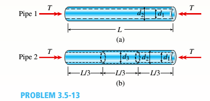
Two circular aluminum pipes of equal length L = 24 in. arc loaded by torsional moments T (sec figure). Pipe I has outside and inside diameters d2= 3 in. and L2, = 2.5 in., respectively. Pipe 2 has a constant outer diameter of d2along its entire length L and an inner diameter of d1but has an increased inner diameter of d3= 2.65 in. over the middle third.
Assume that E = 10,400 ksi, u = 0.33, and allowable shear stress ra= 6500 psi.
- Find the maximum acceptable torques that can be applied to Pipe 1; repeat for Pipe 2.
(a)
The maximum acceptable torques for pipe (1).
The maximum acceptable torques for pipe (2).
Answer to Problem 3.5.13P
Maximum acceptable torques for pipe (1) is =
Maximum acceptable torques for pipe (2) is =
Explanation of Solution
Given information:
The following figure shows the free body diagram of pipe 1:
Figure-(1) shows the diagram of two pipes:
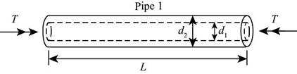
Figure-(1)
The following figure shows the free body diagram of pipe 2:
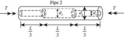
Figure-(2)
The length of pipe is
Write the expression for polar moment of inertia for pipe (1)
Here, the polar moment of inertia is
Write the expression for maximum torque for pipe (1)
Here, acceptable shear stress is
Write the expression for polar moment of inertia for pipe (2)
Here, the polar moment of inertia is
Write the expression for maximum torque for pipe (2)
Here, acceptable shear stress is
Calculation:
Substitute,
Substitute
Substitute,
Substitute
Conclusion:
Maximum acceptable torques for pipe (1) is =
Maximum acceptable torques for pipe (2) is =
(b)
The maximum acceptable length of the middle segment.
Answer to Problem 3.5.13P
The maximum acceptable length of the middle segment.
Explanation of Solution
Given information:
Maximum twist of pipe (2) cannot exceed
Write the expression for the angle of twist for pipe (1).
Here the angle of twist is
Write the expression for total angle of twist for pipe (2)
Here, the total angle of twist is
Write the expression for the length of the segment
Write expression for the angle of twist in the section
Write expression for the angle of twist in the section
Write expression for the angle of twist in the section
Substitute
Write the expression for relation between
Calculation:
Substitute
Substitute
Substitute
Conclusion:
The maximum acceptable length of the middle segment is =
(c)
The inner diameter for the given parameters.
Answer to Problem 3.5.13P
The inner diameter for the given parameters is =
Explanation of Solution
Given information:
the maximum torque carried by pipe (2) is
Write the expression for allowable torque.
Here, the allowable torque is
Substitute
Calculation:
Substitute
Conclusion:
The inner diameter for the given parameters is
(c)
Applied torque on pipe (1)
Maximum twist of pipe (1)
Answer to Problem 3.5.13P
Applied torque on pipe (1) is =
Applied torque on pipe (2) is =
Maximum twist of pipe (1) is =
Explanation of Solution
Write the expression for maximum shear strain.
Here, maximum shear strain is
Write the expression for maximum shear stress.
Here, the maximum shear stress is
Write the expression for shear modulus of elasticity.
Write the expression for maximum torque for pipe (1)
Write the expression for maximum angle of twist for pipe (1)
Maximum angle of twist in pipe (1) is
Calculation:
Substitute
Substitute
Substitute
Substitute
Substitute
Substitute
Conclusion:
Applied torque on pipe (1) is =
Applied torque on pipe (2) is =
Maximum twist of pipe (1) is =
Want to see more full solutions like this?
Chapter 3 Solutions
Mechanics of Materials, SI Edition


- 4: The boom AC is a 4-in. square steel tube with a wallthickness of 0.25 in. The boom is supported by the 0.5-in.-diameter pinat A, and the 0.375-in.-diameter cable BC. The working stresses are 25ksi for the cable, 18 ksi for the boom, and 13.6 ksi for shear in the pin.Neglect the weight of the boom.1. Calculate the maximum value of P (kips) based on boom compression and the maximum value of P (kips) based on tension in the cable.2. Calculate the maximum value of P (kips) based on shear in pin.arrow_forward3: A steel strut S serving as a brace for a boat hoist transmits a compressive force P = 54 kN to the deck of a pier as shown in Fig. STR-08. The strut has a hollow square cross section with a wall thickness t =12mm and the angle θ between the strut and the horizontal is 40°. A pin through the strut transmits the compressive force from the strut to two gusset plates G that are welded to the base plate B. Four anchor bolts fasten the base plate to the deck. The diameter of the pin is 20mm, the thickness of the gusset plates is 16mm, the thickness of the base plate is 8mm, and the diameter of the anchor bolts is 12mm. Disregard any friction between the base plate and the deck.1. Determine the shear stress in the pin, in MPa and the shear stress in the anchor bolts, in MPa.2. Determine the bearing stress in the strut holes, in MPa.arrow_forward1. In the figure, the beam, W410x67, with 9 mm web thicknesssubjects the girder, W530x109 with 12 mm web thickness to a shear load,P (kN). 2L – 90 mm × 90 mm × 6 mm with bolts frame the beam to thegirder.Given: S1 = S2 = S5 = 40 mm; S3 = 75 mm; S4 = 110 mmAllowable Stresses are as follows:Bolt shear stress, Fv = 125 MPaBolt bearing stress, Fp = 510 MPa1. Determine the allowable load, P (kN), based on the shearcapacity of the 4 – 25 mm diameter bolts (4 – d1) and calculate the allowable load, P (kN), based on bolt bearing stress on the web of the beam.2. If P = 450 kN, determine the minimum diameter (mm) of 4 – d1based on allowable bolt shear stress and bearing stress of thebeam web.arrow_forward
- 6: The 6-kN load P is supported by two wooden members of 75 x 125-mm uniform cross section that are joined by the simple glued scarf splice shown.1. Calculate the normal stress in the glue, in MPa.2. Calculate the shear stress in the glue, in MPa.arrow_forwardUsing Matlab calculate the following performance characteristics for a Tesla Model S undergoing the 4506 drive cycle test Prated Trated Ebat 80kW 254 Nm 85kWh/1645kg MUEH A rwheel 0.315M 133.3 C 0.491 Ng ng 7g 8.190.315 8.19 0.315 7ed= 85% Ebpt 35-956 DRIVE AXLE Ebfb chę =85% V Minverter H/A Battery Charger En AC Pry 9) required energy output from the motor to drive this cycle Cassume no regenerative braking) b) range of the Tesla Model S for this drive cycle (assume no regenerative breaking c) estimated mpge cycle of the Tesla Model S for this drive Cassume no regenerative breaking) d) Recalculate parts abc now assuming you can regenerate returns correctly due to inefficiency. from braking. Be careful to handle the diminishing energy braking makes in terms of required e) Quantify the percentage difference that regenerative required energy, range and mpge, DI L Ta a ra OLarrow_forwardHW.5.1 Determine the vertical displacement of joint C on the truss as shown by using Castigliano's theorem. Let E = 200(109) GPa and A = 300 mm² 4 m E 20 kN 3 m 3 m B D 30 kN Carrow_forward
- 3-55 A multifluid container is connected to a U-tube, as shown in Fig. P3–55. For the given specific gravities and fluid column heights, determine the gage pressure at A. Also determine the height of a mercury column that would create the same pressure at A. Answers: 0.415 kPa, 0.311 cmarrow_forwardI need help answering parts a and barrow_forwardRequired information Water initially at 200 kPa and 300°C is contained in a piston-cylinder device fitted with stops. The water is allowed to cool at constant pressure until it exists as a saturated vapor and the piston rests on the stops. Then the water continues to cool until the pressure is 100 kPa. NOTE: This is a multi-part question. Once an answer is submitted, you will be unable to return to this part. Water 200 kPa 300°C On the T-V diagram, sketch, with respect to the saturation lines, the process curves passing through the initial, intermediate, and final states of the water. Label the T, P, and V values for end states on the process curves. Please upload your response/solution by using the controls provided below.arrow_forward
- A piston-cylinder device contains 0.87 kg of refrigerant-134a at -10°C. The piston that is free to move has a mass of 12 kg and a diameter of 25 cm. The local atmospheric pressure is 88 kPa. Now, heat is transferred to refrigerant-134a until the temperature is 15°C. Use data from the tables. R-134a -10°C Determine the change in the volume of the cylinder of the refrigerant-134a if the specific volume and enthalpy of R-134a at the initial state of 90.4 kPa and -10°C and at the final state of 90.4 kPa and 15°C are as follows: = 0.2418 m³/kg, h₁ = 247.77 kJ/kg 3 v2 = 0.2670 m³/kg, and h₂ = 268.18 kJ/kg The change in the volume of the cylinder is marrow_forwardA piston-cylinder device contains 0.87 kg of refrigerant-134a at -10°C. The piston that is free to move has a mass of 12 kg and a diameter of 25 cm. The local atmospheric pressure is 88 kPa. Now, heat is transferred to refrigerant-134a until the temperature is 15°C. Use data from the tables. R-134a -10°C Determine the final pressure of the refrigerant-134a. The final pressure is kPa.arrow_forwardThe hydraulic cylinder BC exerts on member AB a force P directed along line BC. The force P must have a 560-N component perpendicular to member AB. A M 45° 30° C Determine the force component along line AB. The force component along line AB is N.arrow_forward
 Mechanics of Materials (MindTap Course List)Mechanical EngineeringISBN:9781337093347Author:Barry J. Goodno, James M. GerePublisher:Cengage Learning