International Edition---engineering Mechanics: Statics 4th Edition
4th Edition
ISBN: 9781305856240
Author: Pytel
Publisher: Cengage
expand_more
expand_more
format_list_bulleted
Concept explainers
Videos
Textbook Question
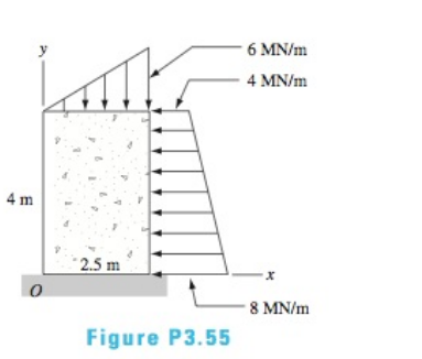
Chapter 3, Problem 3.55P
The concrete pier is subjected to soil pressure that causes the line loads shown. Determine the resultant of the loading and find the y-coordinate of the point where the resultant crosses the y-axis
Expert Solution & Answer

Trending nowThis is a popular solution!

Students have asked these similar questions
The triangular plate, having a 90∘∘ angle at AA, supports the load PP = 370 lblb as shown in (Figure 1).
Design a 4-bar linkage to carry the body in Figure 1 through the two positions P1 and P2 at the
angles shown in the figure. Use analytical synthesis with the free choice values z = 1.075, q=
210°, ß2 = −27° for left side and s = 1.24, y= 74°, ½ = − 40° for right side.
φ
1.236
P2
147.5°
210°
2.138
P1
Figure 1
X
Design a 4-bar linkage to carry the body in Figure 1 through the two positions P1 and P2 at the
angles shown in the figure. Use analytical synthesis with the free choice values z = 1.075, q=
210°, B₂ = −27° for left side and s = 1.24, y= 74°, ½ = − 40° for right side.
1.236
P2
147.5°
210°
P1
Figure 1
2.138
X
Chapter 3 Solutions
International Edition---engineering Mechanics: Statics 4th Edition
Ch. 3 - Determine which of the force systems in (b)...Ch. 3 - Replace the force system acting on the beam by an...Ch. 3 - Replace the force system with an equivalent...Ch. 3 - The four forces shown act on the rollers of an...Ch. 3 - Replace the three forces with an equivalent...Ch. 3 - The force system acting on the machine part is...Ch. 3 - The three forces are perpendicular to the...Ch. 3 - Replace the three forces acting on the...Ch. 3 - When the three forces acting on the...Ch. 3 - Represent each of the force systems with a...
Ch. 3 - A worker applies the forces P=8i+10jlb and Q=8ilb...Ch. 3 - When the three forces are replaced by an...Ch. 3 - Replace the two forces and a couple acting on the...Ch. 3 - The shaft-and-pulley assembly ABCD is driven by...Ch. 3 - Replace the force and the couple with an...Ch. 3 - Determine the resultant force R and its line of...Ch. 3 - The 3200-1b weight is supported by two cables....Ch. 3 - The resultant of the three concurrent forces...Ch. 3 - The overhead electric hoist C rides along a track...Ch. 3 - Determine the resultant of the two forces and the...Ch. 3 - Determine the resultant of the force system shown.Ch. 3 - Determine the resultant of the three forces if (a)...Ch. 3 - Determine the resultant of the force system acting...Ch. 3 - Determine the resultant of the forces shown.Ch. 3 - The resultant of the three forces is a force R...Ch. 3 - The resultant of the four belt tensions and the...Ch. 3 - The resultant of the three forces shown is a...Ch. 3 - The resultant of the three forces is the force...Ch. 3 - The bar AB, which is inclined at the angle to the...Ch. 3 - The values of Fz,Mx, and My for three force...Ch. 3 - State whether the resultant of each force system...Ch. 3 - Determine the resultant of the three cable...Ch. 3 - The resultant of the three cable tensions acts...Ch. 3 - The resultant of the three forces acting along the...Ch. 3 - The resultant of the four forces that act on the...Ch. 3 - Determine the resultant R of the three forces...Ch. 3 - Find the resultant of the three forces acting on...Ch. 3 - The resultant of the forces P1,P2, and the couple...Ch. 3 - Find the resultant of the two forces and the...Ch. 3 - Determine the resultant of the force system acting...Ch. 3 - The wrench shown is the resultant of a...Ch. 3 - Determine the resultant of the four forces.Ch. 3 - The force-couple system acting at O is equivalent...Ch. 3 - The force-couple system consists of the force...Ch. 3 - (a) Replace the force system shown by an...Ch. 3 - During a storm, wind exerts a pressure of 110N/m2,...Ch. 3 - Water pressure acting on the vertical wall of the...Ch. 3 - Determine the resultant of the line load acting on...Ch. 3 - Determine the resultant of the line load acting on...Ch. 3 - Determine the resultant of the line loads acting...Ch. 3 - Find the resultant of the distributed load acting...Ch. 3 - Determine the resultant of the uniformly...Ch. 3 - The figure shows the water pressure acting on the...Ch. 3 - The water pressure acting on a masonry dam varies...Ch. 3 - The concrete pier is subjected to soil pressure...Ch. 3 - Find the resultant of the three forces acting on...Ch. 3 - The resultant of the force system shown is a...Ch. 3 - Determine the resultant of the three forces acting...Ch. 3 - The five forces act at end A of the boom....Ch. 3 - Find the resultant of the distributed load acting...Ch. 3 - Determine the resultant of the line loads acting...Ch. 3 - Replace the force system shown with an equivalent...Ch. 3 - The center of gravity of the 30-lb square plate is...Ch. 3 - Determine the resultant of the force system shown.Ch. 3 - Find the x- and y-coordinates of the point where...Ch. 3 - Replace the force system acting on the pipe with...Ch. 3 - Replace the coplanar force system that acts on the...Ch. 3 - Determine the magnitude of the resultant of the...Ch. 3 - Determine the wrench that is equivalent to the...Ch. 3 - The resultant of the three cable tensions acting...
Knowledge Booster


Learn more about
Need a deep-dive on the concept behind this application? Look no further. Learn more about this topic, mechanical-engineering and related others by exploring similar questions and additional content below.Similar questions
- can you explain how in a coordinate frame transformation: v = {v_n}^T {n-hat} and then it was found that {n-hat} = [C]^T {b-hat} so v_n = {v_n}^T [C]^T {b-hat}, how does that equation go from that to this --> v_n = [C]^T v_barrow_forward6) If (k = 0,7 cm) find Imax for figure below. 225mm 100mm ثلاثاء. 100mm 150mm 75mm Ans: Tmax=45:27 N/cm F-400 Narrow_forwardThe man has a weight W and stands halfway along the beam. The beam is not smooth, but the planes at A and B are smooth (and plane A is horizontal). Determine the magnitude of the tension in the cord in terms of W and θ.arrow_forward
- A 15 cm-OD pipe is buried with its centerline 1.25 m below the surface of the ground [k of soil is 0.35 W/(m K)]. An oil having a density of 800 kg/m³ and a specific heat of 2.1 kJ/(kg K) flows in the pipe at 5.6 L/s. Assuming a ground surface temperature of 5°C and a pipe wall temperature of 95°C, estimate the length of pipe in which the oil temperature decreases by 5.5°C. + Tε = 5ºC Z= 1.25 m D= 15 cm 7p=95°Carrow_forwardFind the solution of the following Differential Equations 1) 4y+y=0, y(0)=2, y'(0) = 0. 2) y+y=0, y(0) = A, y'(0) = B. 3) "+2y'-8y=0, y(0)=1, y'(0)=8. 4) y"-2y-3y=0, y(0)=1, y'(0)=7. 5) y"-ky' =0, y(0)=2, y'(0) =k. 6) y+ky'-2k2y=0, y(0)=2, y'(0) = 2k. 7) y'+4y=0, y(0)=2.8 y+y-17sin(21) y(0)=-1. 9) y-y'-6y=0, y(0)=6. y'(0)=13. 10) y-y=0, 11) y"-4y+4y=0, y(0)=4, y'(0) = 0. y(0) = 2.1, y'(0)=3.9 12) y+2y+2y=0, y(0)=1, y'(0)=-3. 13) "+7y+12y=21e", y(0)=3.5, y'(0)=-10. 14) "+9y=10e", y(0)=0. y'(0) = 0. 15) y+3y+2.25y=91³ +64. y(0)=1, y'(0) = 31.5 16) "-6y+5y= 29 cos(21), y(0)=3.2, y'(0) = 6.2 17) y+2y+2y=0, y(0)=0, y'(0)=1. 18) y+2y+17y=0, y(0)=0, y'(0)=12. 19) y-4y+5y=0, y(0)-1, y'(0) 2. 20) 9y-6y+y=0. y(0)=3, y'(0)=1. 21) -2y+10y=0, y(0)=3, y'(0)=3. 22) 4y-4y+37y=0, (0) 3. y(0) 1.5 23) 4y-8y+5y=0, (0)-0, y(0) 1. 24) y+y+1.25y=0, y(0) 1. y'(0) -0.5 25) y+y=2 cos(1). y(0) 2. y'(0) = 0. 26) -4y+3y=0, (0)-3, y'(0) = 7. 27) y+2y+y=e", y(0)-0. y'(0) = 0. 29) 28) y+2y-3y-10sinh(2),…arrow_forwardNote: Please provide a clear, step-by-step simplified handwritten working out (no explanations!), ensuring it is done without any AI involvement. I require an expert-level answer, and I will assess and rate based on the quality and accuracy of your work and refer to the provided image for more clarity. Make sure to double-check everything for correctness before submitting appreciate your time and effort!. Question:arrow_forward
- 4. Block A and B are two different pieces of wood. Determine the minimum dimension for "a", if the shear stress of the wood is 50Mpa. The thickness of the wood is 30cm. 600N Aarrow_forward1. Determine the reaction force at A. 60 kN 5 B 1 m 1 m- -1 m 4 3 m 30 kN marrow_forwardFind the Laplace Transform of the following functions 1) f() cos(ar) Ans. F(s)=7 2ws 2) f() sin(at) Ans. F(s)= s² + a² 3) f(r)-rcosh(at) Ans. F(s)= 2as 4)(t)=sin(at) Ans. F(s)= 2 5) f(1) = 2te' Ans. F(s)= (S-1) 5+2 6) (1) e cos() Ans. F(s) = (+2)+1 7) (1) (Acostẞr)+ Bsin(Br)) Ans. F(s)- A(s+a)+BB (s+a)+B 8) f()-(-)() Ans. F(s)= 9)(1)(1) Ans. F(s): 10) f(r),()sin() Ans. F(s): 11) 2 k 12) 0 13) 0 70 ㄷ.. a 2a 3a 4a 2 3 4 14) f(1)=1, 0<1<2 15) (1) Ksin(t) 0arrow_forwardarrow_back_iosSEE MORE QUESTIONSarrow_forward_ios
Recommended textbooks for you
 International Edition---engineering Mechanics: St...Mechanical EngineeringISBN:9781305501607Author:Andrew Pytel And Jaan KiusalaasPublisher:CENGAGE L
International Edition---engineering Mechanics: St...
Mechanical Engineering
ISBN:9781305501607
Author:Andrew Pytel And Jaan Kiusalaas
Publisher:CENGAGE L
Types Of loads - Engineering Mechanics | Abhishek Explained; Author: Prime Course;https://www.youtube.com/watch?v=4JVoL9wb5yM;License: Standard YouTube License, CC-BY