Videos
The values of

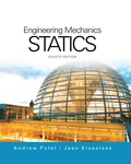
Determine the resultant of each force system and show it on a sketch of the coordinate system.
(a)
The resultant of force system and show it on a sketch of the co-ordinate system.
Answer to Problem 3.30P
The resultant force is -50 k lb.
The resultant moment of the system is
The force system is shown in the co-ordinate system.
Explanation of Solution
Given:
ΣFz = -50 lb.
ΣMX = -250 lb-ft.
ΣMY = 200 lb-ft.
Concept Used:
Calculation:
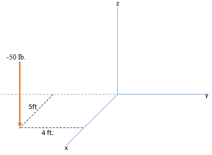
Let a and b be the distances from the x and y- axes respectively.
Conclusion:
The resultant force is -50 k lb.
The resultant moment of the system is
The force system is shown in the co-ordinate system.
(c)
The resultant of force system and show it on a sketch of the co-ordinate system.
Answer to Problem 3.30P
The resultant force is
The resultant moment of the system is
The force system is shown in the co-ordinate system.
Explanation of Solution
Given:
ΣFz = 50 kN.
ΣMX = 0
ΣMY = -250 kN-m.
Concept Used:
Calculation:
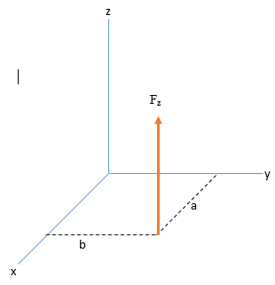
Let a and b be the distances from the x and y- axes respectively.
Conclusion:
The resultant force is
The resultant moment of the system is
The force system is shown in the co-ordinate system.
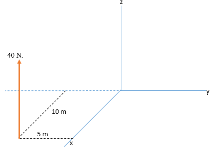
(c)
The resultant of force system and show it on a sketch of the co-ordinate system.
Answer to Problem 3.30P
The resultant force is
The resultant moment of the system is
The force system is shown in the co-ordinate system.
Explanation of Solution
Given:
ΣFz = 40 N.
ΣMX = 320 N.m.
ΣMY = -400 N-m.
Concept Used:
Calculation:

Let a and b be the distances from the x and y- axes respectively.
Conclusion:
The resultant force is
The resultant moment of the system is
The force system is shown in the co-ordinate system.
Want to see more full solutions like this?
Chapter 3 Solutions
International Edition---engineering Mechanics: Statics 4th Edition


- Q1. If the yield stress (σy) of a material is 375MPa, determine whether yield is predicted for the stresses acting on both the elements shown below using: (a) Tresca Criterion (b) Von Mises Criterion P Element A R S Element B Note: your values for P (vertical load on Element A) should be negative (i.e. corresponding to a compressive vertical load).arrow_forwardQ. After a puncture a driver is attempting to remove a wheel nut by applying a force of P KN to one end of a wheel brace as shown in Fig. 1. In cross-section the brace is a hollow steel tube (see section aa) of internal diameter r mm and external diameter q mm. wheel nut n Position S P m r q Section aa Fig, 1 (a) Calculate (i) the twisting moment, (ii) the bending moment, and (iii) the shear force in the brace at position S due to the applied load P. (b) Calculate (i) the shear stress due to twisting, and (ii) the bending stress at position S. Note that the shear force will not produce any shear stress at S. (c) Calculate the maximum shearing stress in the brace at position S using the Maximum Shear Stress Criterion. 2 Mechanics of Materials 2 Tutorials Portfolio: Exercise 5 (d) If the maximum permissible shear stress in the steel is 200 MPa, determine the maximum torque that can be applied by the brace without the risk of failure at S.arrow_forwardCalculate the first 5 Fourier series coefficients (A0-4 and B1-5 ) for the estimated R wave.arrow_forward
- Refrigerant-134a is expanded isentropically from 600 kPa and 70°C at the inlet of a steady-flow turbine to 100 kPa at the outlet. The outlet area is 1 m2, and the inlet area is 0.5 m2. Calculate the inlet and outlet velocities when the mass flow rate is 0.65 kg/s. Use the tables for R-134a. The inlet velocity is m/s. The outlet velocity is m/s.arrow_forwardA container filled with 70 kg of liquid water at 95°C is placed in a 90-m3 room that is initially at 12°C. Thermal equilibrium is established after a while as a result of heat transfer between the water and the air in the room. Assume the room is at the sea level, well sealed, and heavily insulated. NOTE: This is a multi-part question. Once an answer is submitted, you will be unable to return to this part. Determine the final equilibrium temperature. Use the table containing the ideal gas specific heats of various common gases. The final equilibrium temperature is °C.arrow_forwardSteam at 100 psia and 650°F is expanded adiabatically in a closed system to 10 psia. Determine the work produced, in Btu/lbm, and the final temperature of steam for an isentropic expansion efficiency of 80 percent. Use steam tables. The work produced is Btu/lbm. The final temperature of steam is °F.arrow_forward
- Complet the solution : Vavg Ti Te Ts Q hexp Nuexp htheo Re Nutheo Error (m/s) (*C) (*C) (*C) (W) 2.11 18.8 21.3 45.8 2.61 18.5 20.8 46.3arrow_forwardA 48-kg iron block and a 76-kg copper block, both initially at 80°C, are dropped into a large lake at 15°C. Thermal equilibrium is established after a while as a result of heat transfer between the blocks and the lake water. Determine the total entropy change for this process. The specific heat of iron at room temperature is cp = 0.45 kJ/kg·K. The specific heat of copper at 27°C is cp = 0.386 kJ/kg·K. The total entropy change for this process is kJ/K.arrow_forwardPlease help Air at 4.4 MPa and 500°C is expanded in an adiabatic gas turbine to 0.2 MPa. Calculate the maximum work that this turbine can produce in kJ/kg. Use the table containing the ideal gas specific heats of various common gases. The maximum work that this turbine can produce is kJ/kg.arrow_forward
- Saturated water vapor at 150°C is compressed in a reversible steady-flow device to 1150 kPa while its specific volume remains constant. Determine the work required in kJ/kg. Use steam tables. The work required is kJ/kg.arrow_forwardThree lbm of R-134a is expanded isentropically in a closed system from 100 psia and 100°F to 10 psia. Determine the total heat transfer and the work production for this process. Use the tables for R-134a. The total heat transfer is Btu. The work production for this process is Btu. Three lbm of R-134a is expanded isentropically in a closed system from 100 psia and 100°F to 10 psia. Determine the total heat transfer and the work production for this process. Use the tables for R-134a. The total heat transfer is Btu. The work production for this process is Btu.arrow_forwardOxygen at 300 kPa and 90°C flowing at an average velocity of 3 m/s is expanded in an adiabatic nozzle. What is the maximum velocity of the oxygen at the outlet of this nozzle when the outlet pressure is 60 kPa? Use the table containing the ideal gas specific heats of various common gases. The maximum velocity of the oxygen at the outlet of this nozzle is m/s.arrow_forward
 International Edition---engineering Mechanics: St...Mechanical EngineeringISBN:9781305501607Author:Andrew Pytel And Jaan KiusalaasPublisher:CENGAGE L