
Principles Of Electric Circuits
10th Edition
ISBN: 9780134879482
Author: Floyd, Thomas L.
Publisher: Pearson,
expand_more
expand_more
format_list_bulleted
Concept explainers
Videos
Textbook Question
Chapter 3, Problem 32P
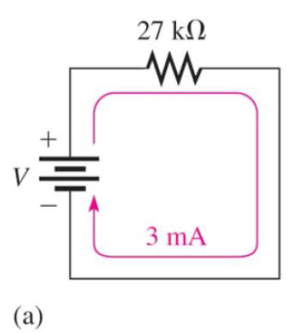
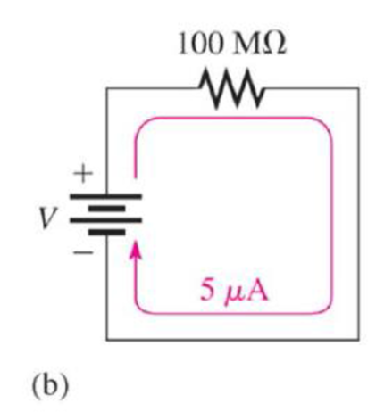
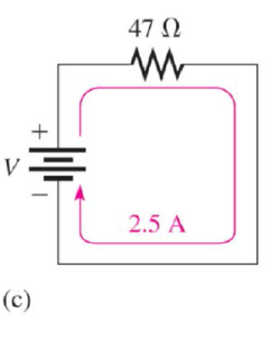
Assign a voltage value to each source in the circuits of Figure 3-26 to obtain the indicated amounts of current.
Figure 3-26
Expert Solution & Answer
Want to see the full answer?
Check out a sample textbook solution
Students have asked these similar questions
Q3.
a) Given the unsymmetrical phasors for a three-phase system, they can be
represented in terms of their symmetrical components as follows:
[Fa]
[1 1
Fb = 1 a²
[Fc.
11[Fao]
a Fai
1 a a2F a2-
where F stands for any three-phase quantity. Conversely, the sequence
components can be derived from the unsymmetrical phasors as:
[11 1] [Fal
Faol
Fa1 =
1 a a² F
1 a²
a
a2.
Given the unbalanced three-phase voltages:
V₁ = 120/10° V, V₂ = 200/110° V, V = 240/200° V
Calculate in polar form the sequence components of the voltage.
Complete the table of values for this circuit:
*P2.58. Solve for the node voltages shown in Figure
P2.58.
-
10 Ω
w
+
10 Ω
15 Ω
w
w
'+'
5 Ω
20x
1 A
Figure P2.58
w
V2
502 12A
Chapter 3 Solutions
Principles Of Electric Circuits
Ch. 3 - If the current drops to 10 mA under the same...Ch. 3 - If the sense resistor develops 0.8 V across it,...Ch. 3 - Calculate the current in Figure 3-71 if R is...Ch. 3 - What is the current in mA produced by 1 kV across...Ch. 3 - How much current is there through a 6.8 M resistor...Ch. 3 - In Figure 3-10, how much voltage is required to...Ch. 3 - lf there are 3.2 A through a 47 resistor, what is...Ch. 3 - If there are 450 A through a 3.9 M resistor, what...Ch. 3 - In the circuit of Figure 3-13, how much resistance...Ch. 3 - If one of the grid wires opens, the current drops...
Ch. 3 - If the resistor is changed in Figure 3-14 so that...Ch. 3 - If the total resistance of a circuit increases and...Ch. 3 - Ohms law for finding resistance is R = I/V.Ch. 3 - When milliamps and kilohms are multiplied...Ch. 3 - If a 10 k resistor is connected to a 10 V source,...Ch. 3 - The current in a fixed resistor is directly...Ch. 3 - Ohms law for finding current is I = V/R.Ch. 3 - When microamps and megohms are multiplied, the...Ch. 3 - When voltage is constant, current is inversely...Ch. 3 - Ohms law for finding voltage is V = I/R.Ch. 3 - When I is plotted as a function of V for a fixed...Ch. 3 - Ohms law states that 1. current equals voltage...Ch. 3 - When the voltage across a resistor is doubled, the...Ch. 3 - When 10 V are applied across a 20 resistor, the...Ch. 3 - When there are 10 mA of current through 1.0 k...Ch. 3 - If 20 V are applied across a resistor and there...Ch. 3 - A current of 250 A through a 4.7 k resistor...Ch. 3 - A resistance of 2.2 M is connected across a 1 kV...Ch. 3 - How much resistance is required to limit the...Ch. 3 - An electric heater draws 2.5 A from a 110 V...Ch. 3 - The current through a flashlight bulb is 20 mA and...Ch. 3 - If the current through a fixed resistor goes from...Ch. 3 - If the voltage across a fixed resistor goes from...Ch. 3 - A variable resistor has 5 V across it. If you...Ch. 3 - If the voltage across a resistor increases from 5...Ch. 3 - If larger voltages are applied and results are...Ch. 3 - If the IV curve for a larger value resistor is...Ch. 3 - If the voltmeter reading changes to 175 V, the...Ch. 3 - If is changed to a larger value and the voltmeter...Ch. 3 - If the resistor is removed from the circuit...Ch. 3 - If the resistor is removed from the circuit...Ch. 3 - If the rheostat is adjusted to increase the...Ch. 3 - If the rheostat is adjusted to increase the...Ch. 3 - If the fuse opens, the voltage across the heating...Ch. 3 - If the source voltage increases, the voltage...Ch. 3 - If the fuse is changed to one with a higher...Ch. 3 - If the lamp burns out (opens), the current a....Ch. 3 - If the lamp burns out, the voltage across it a....Ch. 3 - In a circuit consisting of a voltage source and a...Ch. 3 - State the formula used to find I when the values...Ch. 3 - State the formula used to find V when the values...Ch. 3 - State the formula used to find R when the values...Ch. 3 - A variable voltage source is connected to the...Ch. 3 - In a certain circuit, I = 5 mA when V = 1 V....Ch. 3 - Figure 322 is a graph of current versus voltage...Ch. 3 - Plot the currentvoltage relationship for a...Ch. 3 - Plot the currentvoltage relationship for a...Ch. 3 - Determine the current in each circuit in Figure...Ch. 3 - You are measuring the current in a circuit that is...Ch. 3 - (a) If you wish to increase the amount of current...Ch. 3 - Plot a graph of current versus voltage for voltage...Ch. 3 - Does the graph in Problem 13 indicate a linear...Ch. 3 - Figure 3-24 shows an IV curve for a certain light...Ch. 3 - For the bulb graphed in Figure 3-24, what is the...Ch. 3 - Determine the current in each case: a. V = 5 V, R...Ch. 3 - Determine the current in each case: a. V = 9 V, R...Ch. 3 - Assume 200 mV is across a 330 m current sensing...Ch. 3 - A certain resistor has the following color code:...Ch. 3 - A 4-band resistor is connected across the...Ch. 3 - A 5-band resistor is connected across a 12 V...Ch. 3 - If the voltage in Problem 22 is doubled, will a...Ch. 3 - A certain rear window defroster has a resistance...Ch. 3 - If the voltage of the battery in problem 24 drops...Ch. 3 - The potentiometer connected as a rheostat in...Ch. 3 - A 270 current-limiting resistor has a voltage of...Ch. 3 - A small solar cell is connected to a 27 k...Ch. 3 - Calculate the voltage for each value of I and R:...Ch. 3 - Calculate the voltage for each value of I and R:...Ch. 3 - Three amperes of current are measured through a 27...Ch. 3 - Assign a voltage value to each source in the...Ch. 3 - A 6 V source is connected to a 100 resistor by...Ch. 3 - Calculate the resistance of a rheostat for each...Ch. 3 - Calculate the resistance of a rheostat for each...Ch. 3 - Six volts is applied across a resistor. A current...Ch. 3 - The filament of a lamp in the circuit of Figure...Ch. 3 - A certain electrical device has an unknown...Ch. 3 - By varying the rheostat (variable resistor) in the...Ch. 3 - In the light circuit of Figure 329, identify the...Ch. 3 - Assume you have a 32-light string and one of the...
Additional Engineering Textbook Solutions
Find more solutions based on key concepts
Locate the centroid of the area. Prob. 9-17
INTERNATIONAL EDITION---Engineering Mechanics: Statics, 14th edition (SI unit)
Why is the study of database technology important?
Database Concepts (8th Edition)
3.3 It is known that a vertical force of 200 lb is required to remove the nail at C from the board. As the nail...
Vector Mechanics for Engineers: Statics
Assume a telephone signal travels through a cable at two-thirds the speed of light. How long does it take the s...
Electric Circuits. (11th Edition)
What are the design issues for character string types?
Concepts Of Programming Languages
The solid steel shaft AC has a diameter of 25 mm and is supported by smooth bearings at D and E. It is coupled ...
Mechanics of Materials (10th Edition)
Knowledge Booster


Learn more about
Need a deep-dive on the concept behind this application? Look no further. Learn more about this topic, electrical-engineering and related others by exploring similar questions and additional content below.Similar questions
- An 18.65 kW, 4-pole, 50 Hz, 3-phase induction motor has friction and windage losses of 2.5% of the output. The full-load slip is 4%. Find for full-load (i) the rotor cu loss (ii) the rotor input power (iii) the output torque.arrow_forwardQ1: Consider the finite state machine logic implementation in Fig. shown below: a. b. Construct the state diagram. Repeat the circuit design using j-k flip flop. C'lk A D 10 Clk Q D 32 Cik O 31 Please solve the question on a sheet of paper by hand and explain everything related to the question step by step.arrow_forwardAnot ined sove in peaper S PU +96 An 18.65 kW, 4-pole, 50 Hz, 3-phase induction motor has friction and windage losses of 2.5% of the output. The full-load slip is 4 %. Find for full-load (i) the rotor cu loss (ii) the rotor input power (iii) the output torque. 750 1 T el Marrow_forward
- Alternator has star-connected,4-pole, 50 Hz as the following data: Flux per pole-0.12 Wb; No. of slot/pole/phase=4; conductor/slot=4; Each coil spans 150° (electrical degree) pitches Find (i) number of turns per phase (ii) distribution factor (iii) pitch factor (iv) no-load phase voltage (v) no-load line voltage.arrow_forwardAlternator has star-connected,4-pole, 50 Hz as the following data: Flux per pole-0.12 Wb; No. of slot/pole/phase=4; conductor/slot=4; Each coil spans 150° (electrical degree) pitches Find (i) number of turns per phase (ii) distribution factor (iii) pitch factor (iv) no-load phase voltage (v) no-load line voltage.arrow_forwardA) Suppose you were desiging a circuit that required two LEDs for "power on" indication. The power supply voltage is 5 volts, and each LED is rated at 1.6 volts and 20 mA. Calculate the dropping resistor sizes and power ratings: B) After doing this, a co-worker looks at your circuit and suggests a modification. Why not use a single dropping resistor for both LEDs, economizing the number of components necessary? Re-calculate the dropping resistor ratings (resistance and power) for the new design. Include the total power consumed by the circuit and the power delivered by the source.arrow_forward
- S A L ined sove in peaper ۳/۱ 16852 Alternator has star-connected,4-pole, 50 Hz as the following data: Flux per pole-0.12 Wb; No. of slot/pole/phase-4; conductor/slot-4; Each coil spans 150° (electrical degree) pitches Find (i) number of turns per phase (ii) distribution factor (iii) pitch factor (iv) no-load phase voltage (v) no-load line voltage. 2ci25 750 r 2.01 ४arrow_forwardA) Complete the table of values for this circuit: B) Draw the schematic include polarityarrow_forward(choose R1, R2, R3, R4, R5 and assume that 300 β = , all resistors must be greater than zero) such that the following specifications are met: • Minimum open loop gain, Aol, 40dB (can be more, this is the minimum requirement) • Input current (at input terminals) <1uA • Power dissipation DC P ≤20mW • VCC=10V, VEE=0VI NEED HELP, I WANT ONLY TO CALCULATE THE RESISTORSarrow_forward
- 80 V 300 Ω t = 0 500 i(t) Vc(t) 40 nF 2,5 mH -arrow_forwardProblem 1: Two-Force Equilibrium A 12 kg traffic light is suspended by two cables attached to a ceiling. Determine the force in Cable 1 (AB) and Cable 2 (AC). In other words, determine the tension in each cable, assuming the system is in static equilibrium. Barrow_forwardIf the Z-axis changes, what is the effect A circularly polarized wave, traveling in the +z-direction, is received by an elliptically polarized antenna whose reception characteristics near the main lobe are given approx- imately by E₁ = (2â, + jâ] f(r. 8. d) Find the polarization loss factor PLF (dimensionless and in dB) when the incident wave is (a) right-hand (CW) (b) left-hand (CCW) An elliptically polarized wave traveling in the negative z-direction is received by a circularly polarized antenna. The vector describing the polarization of the incident wave is given by Ei= 2ax + jay .Find the polarization loss factor PLF (dimensionless and in dB) when the wave that would be transmitted by the antenna is (a) right-hand CP (b) left-hand CP.arrow_forward
arrow_back_ios
SEE MORE QUESTIONS
arrow_forward_ios
Recommended textbooks for you
 Electricity for Refrigeration, Heating, and Air C...Mechanical EngineeringISBN:9781337399128Author:Russell E. SmithPublisher:Cengage Learning
Electricity for Refrigeration, Heating, and Air C...
Mechanical Engineering
ISBN:9781337399128
Author:Russell E. Smith
Publisher:Cengage Learning
Z Parameters - Impedance Parameters; Author: Electrical Engineering Authority;https://www.youtube.com/watch?v=qoD4AoNmySA;License: Standard Youtube License