
Principles Of Electric Circuits
10th Edition
ISBN: 9780134879482
Author: Floyd, Thomas L.
Publisher: Pearson,
expand_more
expand_more
format_list_bulleted
Concept explainers
Videos
Textbook Question
Chapter 3, Problem 37P
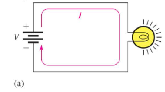
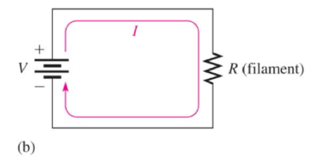
The filament of a lamp in the circuit of Figure 3-27(a) has a certain amount of resistance, represented by an equivalent resistance in Figure 3-27(b). If the lamp operates with 120 V and 0.8 A of current, what is the resistance of its filament when it is on?
Figure 3-27
Expert Solution & Answer
Want to see the full answer?
Check out a sample textbook solution
Students have asked these similar questions
electric plants.
Draw the lighting, socket, telephone, TV, and doorbell installations on the given single-story project with an architectural plan by hand writing
A circularly polarized wave, traveling in the +z-direction, is received by an elliptically
polarized antenna whose reception characteristics near the main lobe are given approx-
imately by
E„ = [2â, + jâ‚]ƒ(r. 8, 4)
Find the polarization loss factor PLF (dimensionless and in dB) when the incident wave
is
(a) right-hand (CW)
An elliptically polarized wave traveling in the negative z-direction is received by a circularly polarized
antenna. The vector describing the polarization of the incident wave is given by Ei= 2ax + jay.Find the
polarization loss factor PLF (dimensionless and in dB) when the wave that would be transmitted by the
antenna is (a) right-hand CP
jX(1)=j0.2p.u.
jXa(2)=j0.15p.u.
jxa(0)=0.15 p.u.
V₁=1/0°p.u.
V₂=1/0° p.u.
1
jXr(1) = j0.15 p.11.
jXT(2) = j0.15 p.u.
jXr(0) = j0.15 p.u.
V3=1/0° p.u.
А
V4=1/0° p.u.
2 jX1(1)=j0.12 p.u. 3 jX2(1)=j0.15 p.u. 4
jX1(2)=0.12 p.11.
JX1(0)=0.3 p.u.
jX/2(2)=j0.15 p.11.
X2(0)=/0.25 p.1.
Figure 1. Circuit for Q3 b).
Chapter 3 Solutions
Principles Of Electric Circuits
Ch. 3 - If the current drops to 10 mA under the same...Ch. 3 - If the sense resistor develops 0.8 V across it,...Ch. 3 - Calculate the current in Figure 3-71 if R is...Ch. 3 - What is the current in mA produced by 1 kV across...Ch. 3 - How much current is there through a 6.8 M resistor...Ch. 3 - In Figure 3-10, how much voltage is required to...Ch. 3 - lf there are 3.2 A through a 47 resistor, what is...Ch. 3 - If there are 450 A through a 3.9 M resistor, what...Ch. 3 - In the circuit of Figure 3-13, how much resistance...Ch. 3 - If one of the grid wires opens, the current drops...
Ch. 3 - If the resistor is changed in Figure 3-14 so that...Ch. 3 - If the total resistance of a circuit increases and...Ch. 3 - Ohms law for finding resistance is R = I/V.Ch. 3 - When milliamps and kilohms are multiplied...Ch. 3 - If a 10 k resistor is connected to a 10 V source,...Ch. 3 - The current in a fixed resistor is directly...Ch. 3 - Ohms law for finding current is I = V/R.Ch. 3 - When microamps and megohms are multiplied, the...Ch. 3 - When voltage is constant, current is inversely...Ch. 3 - Ohms law for finding voltage is V = I/R.Ch. 3 - When I is plotted as a function of V for a fixed...Ch. 3 - Ohms law states that 1. current equals voltage...Ch. 3 - When the voltage across a resistor is doubled, the...Ch. 3 - When 10 V are applied across a 20 resistor, the...Ch. 3 - When there are 10 mA of current through 1.0 k...Ch. 3 - If 20 V are applied across a resistor and there...Ch. 3 - A current of 250 A through a 4.7 k resistor...Ch. 3 - A resistance of 2.2 M is connected across a 1 kV...Ch. 3 - How much resistance is required to limit the...Ch. 3 - An electric heater draws 2.5 A from a 110 V...Ch. 3 - The current through a flashlight bulb is 20 mA and...Ch. 3 - If the current through a fixed resistor goes from...Ch. 3 - If the voltage across a fixed resistor goes from...Ch. 3 - A variable resistor has 5 V across it. If you...Ch. 3 - If the voltage across a resistor increases from 5...Ch. 3 - If larger voltages are applied and results are...Ch. 3 - If the IV curve for a larger value resistor is...Ch. 3 - If the voltmeter reading changes to 175 V, the...Ch. 3 - If is changed to a larger value and the voltmeter...Ch. 3 - If the resistor is removed from the circuit...Ch. 3 - If the resistor is removed from the circuit...Ch. 3 - If the rheostat is adjusted to increase the...Ch. 3 - If the rheostat is adjusted to increase the...Ch. 3 - If the fuse opens, the voltage across the heating...Ch. 3 - If the source voltage increases, the voltage...Ch. 3 - If the fuse is changed to one with a higher...Ch. 3 - If the lamp burns out (opens), the current a....Ch. 3 - If the lamp burns out, the voltage across it a....Ch. 3 - In a circuit consisting of a voltage source and a...Ch. 3 - State the formula used to find I when the values...Ch. 3 - State the formula used to find V when the values...Ch. 3 - State the formula used to find R when the values...Ch. 3 - A variable voltage source is connected to the...Ch. 3 - In a certain circuit, I = 5 mA when V = 1 V....Ch. 3 - Figure 322 is a graph of current versus voltage...Ch. 3 - Plot the currentvoltage relationship for a...Ch. 3 - Plot the currentvoltage relationship for a...Ch. 3 - Determine the current in each circuit in Figure...Ch. 3 - You are measuring the current in a circuit that is...Ch. 3 - (a) If you wish to increase the amount of current...Ch. 3 - Plot a graph of current versus voltage for voltage...Ch. 3 - Does the graph in Problem 13 indicate a linear...Ch. 3 - Figure 3-24 shows an IV curve for a certain light...Ch. 3 - For the bulb graphed in Figure 3-24, what is the...Ch. 3 - Determine the current in each case: a. V = 5 V, R...Ch. 3 - Determine the current in each case: a. V = 9 V, R...Ch. 3 - Assume 200 mV is across a 330 m current sensing...Ch. 3 - A certain resistor has the following color code:...Ch. 3 - A 4-band resistor is connected across the...Ch. 3 - A 5-band resistor is connected across a 12 V...Ch. 3 - If the voltage in Problem 22 is doubled, will a...Ch. 3 - A certain rear window defroster has a resistance...Ch. 3 - If the voltage of the battery in problem 24 drops...Ch. 3 - The potentiometer connected as a rheostat in...Ch. 3 - A 270 current-limiting resistor has a voltage of...Ch. 3 - A small solar cell is connected to a 27 k...Ch. 3 - Calculate the voltage for each value of I and R:...Ch. 3 - Calculate the voltage for each value of I and R:...Ch. 3 - Three amperes of current are measured through a 27...Ch. 3 - Assign a voltage value to each source in the...Ch. 3 - A 6 V source is connected to a 100 resistor by...Ch. 3 - Calculate the resistance of a rheostat for each...Ch. 3 - Calculate the resistance of a rheostat for each...Ch. 3 - Six volts is applied across a resistor. A current...Ch. 3 - The filament of a lamp in the circuit of Figure...Ch. 3 - A certain electrical device has an unknown...Ch. 3 - By varying the rheostat (variable resistor) in the...Ch. 3 - In the light circuit of Figure 329, identify the...Ch. 3 - Assume you have a 32-light string and one of the...
Knowledge Booster


Learn more about
Need a deep-dive on the concept behind this application? Look no further. Learn more about this topic, electrical-engineering and related others by exploring similar questions and additional content below.Similar questions
- can you show me full workings for this problem. the solution is - v0 = 10i2 = 2.941 volts, i0 = i1 – i2 = (5/3)i2 = 490.2mA.arrow_forwardQ4. a) Consider a transmission line modelled as a four-terminal network with an unknown configuration. You are provided with the following measured parameters at the operating frequency: Open-circuit voltage ratio: 0.9521° • Short-circuit impedance: 40+j80 • Open-circuit admittance: -j2 × 10-4 S Use the four terminal equations and the provided measurements to mathematically derive the A, B, C, and D parameters of the network and explain their physical significance. Show your work and formulas used in the derivation.arrow_forwardQ1. Consider a single-phase step-down transformer with primary and secondary turns of 600 and 100 respectively and a primary voltage of 11 kV. (i) An open circuit test was conducted on the transformer and the primary current was measured as: I₁ = 2.20 A Use these results to calculate the magnetising reactance in the equivalent circuit (X) given that Rm, representing the core loss, has a value of 21 km. (ii) The remaining equivalent circuit parameters are as follows: R₁ = 40, X₁ = 25 N, R₂ = 0.4 N, X₂ = 0.3 N Draw the complete simplified equivalent circuit, by referring series components on the primary side to the secondary, giving all component values. (iii) The transformer is connected, on its secondary side, to a load of 10 at a power factor of 1. Calculate the voltage across the load. (iv) Calculate the efficiency of the transformer when operating at the load given in part (iii).arrow_forward
- b) A 132 kV supply feeds a line of reactance 15 which is connected to a 100 MVA, 132/33 kV transformer of 0.08 p.u. reactance as shown in the Figure 2. The transformer feeds a 33 kV line of reactance 8 Q, which, in turn, is connected to a 75 MVA, 33/11 KV transformer of 0.12 p.u. reactance. The transformer supplies an 11 KV substation from which a local 11 kV feeder of 4 Q reactance is supplied. T1 T2 132 kV 33 kV 11 kV Fault X CB Relay Figure 2. Network for Q4 b). (i) Given the system base of 100 MVA, compute the total equivalent reactance of the radial circuit in per unit (p.u.). (ii) Determine the three-phase fault current at the load end of the 11 kV feeder, assuming a fault impedance of 0.05 Q. Calculate the fault current in Amperes. (iii) The 11 kV feeder connects to a protective overcurrent relay via 200/5 A current transformers. This relay has a standard normally inverse IDMT characteristic, with a setting current of 3 A and a time multiplier setting of 0.4. Calculate the…arrow_forwardQ2. a) Two three-phase transformers, designated A and B, have the following secondary equivalent circuit parameters per phase: R₁ = 0.002 Q, XA = 0.03 Q, RB = 0.004 Q, X = 0.012 Q Transformer A is 250 kVA and transformer B is 450 kVA. Calculate how they share a load of 650 KVA when connected in parallel (assume the voltage ratios are equal) b) A step-up transformer is being specified for the beginning of a 3-phase, 4 wire high voltage transmission line. Discuss your recommendation for the configuration of the transformer connections on both the primary and secondary side of the transformer. c) Define power system protection and describe its fundamental purpose. Discuss the following key concepts including discrimination, stability, speed of operation, sensitivity, and reliability in the context of the power system protection components and schemes.arrow_forwardQ3. a) Given the unsymmetrical phasors for a three-phase system, they can be represented in terms of their symmetrical components as follows: [Fa] [1 1 Fb = 1 a² [Fc. 11[Fao] a Fai 1 a a2F a2- where F stands for any three-phase quantity. Conversely, the sequence components can be derived from the unsymmetrical phasors as: [11 1] [Fal Faol Fa1 = 1 a a² F 1 a² a a2. Given the unbalanced three-phase voltages: V₁ = 120/10° V, V₂ = 200/110° V, V = 240/200° V Calculate in polar form the sequence components of the voltage.arrow_forward
- Complete the table of values for this circuit:arrow_forward*P2.58. Solve for the node voltages shown in Figure P2.58. - 10 Ω w + 10 Ω 15 Ω w w '+' 5 Ω 20x 1 A Figure P2.58 w V2 502 12Aarrow_forwardAn 18.65 kW, 4-pole, 50 Hz, 3-phase induction motor has friction and windage losses of 2.5% of the output. The full-load slip is 4%. Find for full-load (i) the rotor cu loss (ii) the rotor input power (iii) the output torque.arrow_forward
- Q1: Consider the finite state machine logic implementation in Fig. shown below: a. b. Construct the state diagram. Repeat the circuit design using j-k flip flop. C'lk A D 10 Clk Q D 32 Cik O 31 Please solve the question on a sheet of paper by hand and explain everything related to the question step by step.arrow_forwardAnot ined sove in peaper S PU +96 An 18.65 kW, 4-pole, 50 Hz, 3-phase induction motor has friction and windage losses of 2.5% of the output. The full-load slip is 4 %. Find for full-load (i) the rotor cu loss (ii) the rotor input power (iii) the output torque. 750 1 T el Marrow_forwardAlternator has star-connected,4-pole, 50 Hz as the following data: Flux per pole-0.12 Wb; No. of slot/pole/phase=4; conductor/slot=4; Each coil spans 150° (electrical degree) pitches Find (i) number of turns per phase (ii) distribution factor (iii) pitch factor (iv) no-load phase voltage (v) no-load line voltage.arrow_forward
arrow_back_ios
SEE MORE QUESTIONS
arrow_forward_ios
Recommended textbooks for you
 Electricity for Refrigeration, Heating, and Air C...Mechanical EngineeringISBN:9781337399128Author:Russell E. SmithPublisher:Cengage Learning
Electricity for Refrigeration, Heating, and Air C...
Mechanical Engineering
ISBN:9781337399128
Author:Russell E. Smith
Publisher:Cengage Learning
Photoelectric Effect, Work Function, Threshold Frequency, Wavelength, Speed & Kinetic Energy, Electr; Author: The Organic Chemistry Tutor;https://www.youtube.com/watch?v=-LECEvusk8E;License: Standard Youtube License