
Principles Of Electric Circuits
10th Edition
ISBN: 9780134879482
Author: Floyd, Thomas L.
Publisher: Pearson,
expand_more
expand_more
format_list_bulleted
Concept explainers
Videos
Textbook Question
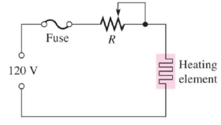
Chapter 3, Problem 11CDQ
If the rheostat is adjusted to increase the resistance, the current through the heating element
- a. increases
- b. decreases
- c. stays the same
Figure 3–25
Expert Solution & Answer
Want to see the full answer?
Check out a sample textbook solution
Students have asked these similar questions
please show full working. I've included the solution
can you please show working and steps. The answer is 8kohms.
PSD
A certain signal f(t) has the following PSD (assume 12 load):
| Sƒ(w) = π[e¯\w\ + 8(w − 2) + +8(w + 2)]
(a) What is the mean power in the bandwidth w≤ 1 rad/sec?
(b) What is the mean power in the bandwidth 0.99 to 1.01 rad/sec?
(c) What is the mean power in the bandwidth 1.99 to 2.01 rad/sec?
(d) What is the total mean power in (t)?
Pav=
+
2T
SfLw) dw
- SALW)
Chapter 3 Solutions
Principles Of Electric Circuits
Ch. 3 - If the current drops to 10 mA under the same...Ch. 3 - If the sense resistor develops 0.8 V across it,...Ch. 3 - Calculate the current in Figure 3-71 if R is...Ch. 3 - What is the current in mA produced by 1 kV across...Ch. 3 - How much current is there through a 6.8 M resistor...Ch. 3 - In Figure 3-10, how much voltage is required to...Ch. 3 - lf there are 3.2 A through a 47 resistor, what is...Ch. 3 - If there are 450 A through a 3.9 M resistor, what...Ch. 3 - In the circuit of Figure 3-13, how much resistance...Ch. 3 - If one of the grid wires opens, the current drops...
Ch. 3 - If the resistor is changed in Figure 3-14 so that...Ch. 3 - If the total resistance of a circuit increases and...Ch. 3 - Ohms law for finding resistance is R = I/V.Ch. 3 - When milliamps and kilohms are multiplied...Ch. 3 - If a 10 k resistor is connected to a 10 V source,...Ch. 3 - The current in a fixed resistor is directly...Ch. 3 - Ohms law for finding current is I = V/R.Ch. 3 - When microamps and megohms are multiplied, the...Ch. 3 - When voltage is constant, current is inversely...Ch. 3 - Ohms law for finding voltage is V = I/R.Ch. 3 - When I is plotted as a function of V for a fixed...Ch. 3 - Ohms law states that 1. current equals voltage...Ch. 3 - When the voltage across a resistor is doubled, the...Ch. 3 - When 10 V are applied across a 20 resistor, the...Ch. 3 - When there are 10 mA of current through 1.0 k...Ch. 3 - If 20 V are applied across a resistor and there...Ch. 3 - A current of 250 A through a 4.7 k resistor...Ch. 3 - A resistance of 2.2 M is connected across a 1 kV...Ch. 3 - How much resistance is required to limit the...Ch. 3 - An electric heater draws 2.5 A from a 110 V...Ch. 3 - The current through a flashlight bulb is 20 mA and...Ch. 3 - If the current through a fixed resistor goes from...Ch. 3 - If the voltage across a fixed resistor goes from...Ch. 3 - A variable resistor has 5 V across it. If you...Ch. 3 - If the voltage across a resistor increases from 5...Ch. 3 - If larger voltages are applied and results are...Ch. 3 - If the IV curve for a larger value resistor is...Ch. 3 - If the voltmeter reading changes to 175 V, the...Ch. 3 - If is changed to a larger value and the voltmeter...Ch. 3 - If the resistor is removed from the circuit...Ch. 3 - If the resistor is removed from the circuit...Ch. 3 - If the rheostat is adjusted to increase the...Ch. 3 - If the rheostat is adjusted to increase the...Ch. 3 - If the fuse opens, the voltage across the heating...Ch. 3 - If the source voltage increases, the voltage...Ch. 3 - If the fuse is changed to one with a higher...Ch. 3 - If the lamp burns out (opens), the current a....Ch. 3 - If the lamp burns out, the voltage across it a....Ch. 3 - In a circuit consisting of a voltage source and a...Ch. 3 - State the formula used to find I when the values...Ch. 3 - State the formula used to find V when the values...Ch. 3 - State the formula used to find R when the values...Ch. 3 - A variable voltage source is connected to the...Ch. 3 - In a certain circuit, I = 5 mA when V = 1 V....Ch. 3 - Figure 322 is a graph of current versus voltage...Ch. 3 - Plot the currentvoltage relationship for a...Ch. 3 - Plot the currentvoltage relationship for a...Ch. 3 - Determine the current in each circuit in Figure...Ch. 3 - You are measuring the current in a circuit that is...Ch. 3 - (a) If you wish to increase the amount of current...Ch. 3 - Plot a graph of current versus voltage for voltage...Ch. 3 - Does the graph in Problem 13 indicate a linear...Ch. 3 - Figure 3-24 shows an IV curve for a certain light...Ch. 3 - For the bulb graphed in Figure 3-24, what is the...Ch. 3 - Determine the current in each case: a. V = 5 V, R...Ch. 3 - Determine the current in each case: a. V = 9 V, R...Ch. 3 - Assume 200 mV is across a 330 m current sensing...Ch. 3 - A certain resistor has the following color code:...Ch. 3 - A 4-band resistor is connected across the...Ch. 3 - A 5-band resistor is connected across a 12 V...Ch. 3 - If the voltage in Problem 22 is doubled, will a...Ch. 3 - A certain rear window defroster has a resistance...Ch. 3 - If the voltage of the battery in problem 24 drops...Ch. 3 - The potentiometer connected as a rheostat in...Ch. 3 - A 270 current-limiting resistor has a voltage of...Ch. 3 - A small solar cell is connected to a 27 k...Ch. 3 - Calculate the voltage for each value of I and R:...Ch. 3 - Calculate the voltage for each value of I and R:...Ch. 3 - Three amperes of current are measured through a 27...Ch. 3 - Assign a voltage value to each source in the...Ch. 3 - A 6 V source is connected to a 100 resistor by...Ch. 3 - Calculate the resistance of a rheostat for each...Ch. 3 - Calculate the resistance of a rheostat for each...Ch. 3 - Six volts is applied across a resistor. A current...Ch. 3 - The filament of a lamp in the circuit of Figure...Ch. 3 - A certain electrical device has an unknown...Ch. 3 - By varying the rheostat (variable resistor) in the...Ch. 3 - In the light circuit of Figure 329, identify the...Ch. 3 - Assume you have a 32-light string and one of the...
Knowledge Booster


Learn more about
Need a deep-dive on the concept behind this application? Look no further. Learn more about this topic, electrical-engineering and related others by exploring similar questions and additional content below.Similar questions
- An AM modulation waveform signal:- p(t)=(8+4 cos 1000πt + 4 cos 2000πt) cos 10000nt (a) Sketch the amplitude spectrum of p(t). (b) Find total power, sideband power and power efficiency. (c) Find the average power containing of each sideband.arrow_forwardCan you rewrite the solution because it is unclear? AM (+) = 8(1+ 0.5 cos 1000kt +0.5 ros 2000ks) = cos 10000 πt. 8 cos wat + 4 cos wit + 4 cos Wat coswet. -Jet jooort J11000 t = 4 e jqooort jgoort +4e + e +e j 12000rt. 12000 kt + e +e jooxt igoo t te (w) = 8ES(W- 100007) + 8IS (W-10000) USBarrow_forwardCan you rewrite the solution because it is unclear? AM (+) = 8(1+0.5 cos 1000kt +0.5 ros 2000 thts) = cos 10000 πt. 8 cos wat + 4 cos wit + 4 cos Wat coswet. J4000 t j11000rt $14+) = 45 jqooort +4e + e + e j 12000rt. 12000 kt + e +e +e Le jsoort -; goon t te +e Dcw> = 885(W- 100007) + 8 IS (W-10000) - USBarrow_forward
- Can you rewrite the solution because it is unclear? Q2 AM ①(+) = 8 (1+0.5 cos 1000πt +0.5 ros 2000kt) $4+) = 45 = *cos 10000 πt. 8 cos wat + 4 cosat + 4 cos Wat coswet. j1000016 +4e -j10000πt j11000Rt j gooort -j 9000 πt + e +e j sooort te +e J11000 t + e te j 12000rt. -J12000 kt + с = 8th S(W- 100007) + 8 IS (W-10000) <&(w) = USB -5-5 -4-5-4 b) Pc 2² = 64 PSB = 42 + 4 2 Pt Pc+ PSB = y = Pe c) Puss = PLSB = = 32 4² = 8 w 32+ 8 = × 100% = 140 (1)³×2×2 31 = 20% x 2 = 3w 302 USB 4.5 5 5.6 6 ms Ac = 4 mi = 0.5 mz Ac = 4 ५ M2 = =0.5arrow_forwardA. Draw the waveform for the following binary sequence using Bipolar RZ, Bipolar NRZ, and Manchester code. Data sequence= (00110100) B. In a binary PCM system, the output signal-to-quantization ratio is to be hold to a minimum of 50 dB. If the message is a single tone with fm-5 kHz. Determine: 1) The number of required levels, and the corresponding output signal-to-quantizing noise ratio. 2) Minimum required system bandwidth.arrow_forwardFind Io using Mesh analysisarrow_forward
- FM station of 100 MHz carrier frequency modulated by a 20 kHz sinusoid with an amplitude of 10 volt, so that the peak frequency deviation is 25 kHz determine: 1) The BW of the FM signal. 2) The approximated BW if the modulating signal amplitude is increased to 50 volt. 3) The approximated BW if the modulating signal frequency is increased by 70%. 4) The amplitude of the modulating signal if the BW is 65 kHz.arrow_forwardAn FDM is used to multiplex two groups of signals using AM-SSB, the first group contains 25 speech signals, each has maximum frequency of 4 kHz, the second group contains 15 music signals, each has maximum frequency of 10 kHz. A guard bandwidth of 500 Hz is used bety each two signals and before the first one. 1. Find the BWmultiplexing 2. Find the BWtransmission if the multiplexing signal is modulated using AM-DSB-LC.arrow_forwardAn FM signal with 75 kHz deviation, has an input signal-to-noise ratio of 18 dB, with a modulating frequency of 15 kHz. 1) Find SNRO at demodulator o/p. 2) Find SNRO at demodulator o/p if AM is used with m=0.3. 3) Compare the performance in case 1) and 2).. Hint: for single tone AM-DSB-LC, SNR₁ = (2m²) (4)arrow_forward
arrow_back_ios
SEE MORE QUESTIONS
arrow_forward_ios
Recommended textbooks for you
 EBK ELECTRICAL WIRING RESIDENTIALElectrical EngineeringISBN:9781337516549Author:SimmonsPublisher:CENGAGE LEARNING - CONSIGNMENT
 Electricity for Refrigeration, Heating, and Air C...Mechanical EngineeringISBN:9781337399128Author:Russell E. SmithPublisher:Cengage Learning
 Power System Analysis and Design (MindTap Course ...Electrical EngineeringISBN:9781305632134Author:J. Duncan Glover, Thomas Overbye, Mulukutla S. SarmaPublisher:Cengage Learning
 Delmar's Standard Textbook Of ElectricityElectrical EngineeringISBN:9781337900348Author:Stephen L. HermanPublisher:Cengage Learning
EBK ELECTRICAL WIRING RESIDENTIAL
Electrical Engineering
ISBN:9781337516549
Author:Simmons
Publisher:CENGAGE LEARNING - CONSIGNMENT
Electricity for Refrigeration, Heating, and Air C...
Mechanical Engineering
ISBN:9781337399128
Author:Russell E. Smith
Publisher:Cengage Learning
Power System Analysis and Design (MindTap Course ...
Electrical Engineering
ISBN:9781305632134
Author:J. Duncan Glover, Thomas Overbye, Mulukutla S. Sarma
Publisher:Cengage Learning
Delmar's Standard Textbook Of Electricity
Electrical Engineering
ISBN:9781337900348
Author:Stephen L. Herman
Publisher:Cengage Learning
Kirchhoff's Rules of Electrical Circuits; Author: Flipping Physics;https://www.youtube.com/watch?v=d0O-KUKP4nM;License: Standard YouTube License, CC-BY