EBK MACHINE ELEMENTS IN MECHANICAL DESI
6th Edition
ISBN: 9780134451947
Author: Wang
Publisher: YUZU
expand_more
expand_more
format_list_bulleted
Concept explainers
Videos
Textbook Question
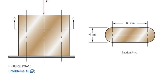
Chapter 3, Problem 15P
Consider the short compression member shown in Figure P3−15. Compute the compressive stress if the cross section has the shape shown and the applied load is 640 kN.
Expert Solution & Answer
Want to see the full answer?
Check out a sample textbook solution
Students have asked these similar questions
Please help
Air at 4.4 MPa and 500°C is expanded in an adiabatic gas turbine to 0.2 MPa. Calculate the maximum work that this turbine can produce in kJ/kg. Use the table containing the ideal gas specific heats of various common gases.
The maximum work that this turbine can produce is kJ/kg.
Saturated water vapor at 150°C is compressed in a reversible steady-flow device to 1150 kPa while its specific volume remains constant. Determine the work required in kJ/kg. Use steam tables.
The work required is kJ/kg.
Three lbm of R-134a is expanded isentropically in a closed system from 100 psia and 100°F to 10 psia. Determine the total heat transfer and the work production for this process. Use the tables for R-134a.
The total heat transfer is Btu.
The work production for this process is Btu.
Three lbm of R-134a is expanded isentropically in a closed system from 100 psia and 100°F to 10 psia. Determine the total heat transfer and the work production for this process. Use the tables for R-134a.
The total heat transfer is Btu.
The work production for this process is Btu.
Chapter 3 Solutions
EBK MACHINE ELEMENTS IN MECHANICAL DESI
Ch. 3 - A tensile member in a machine structure is...Ch. 3 - Compute the stress in a round bar having a...Ch. 3 - Compute the stress in a rectangular bar having...Ch. 3 - A link in a packaging machine mechanism has a...Ch. 3 - Two circular rods support the 3800 lb weight of a...Ch. 3 - A tensile load of 5.00 kN is applied to a square...Ch. 3 - An aluminum rod is made in the form of a hollow...Ch. 3 - Compute the stress in the middle portion of rod AC...Ch. 3 - Compute the forces in the two angled rods in...Ch. 3 - If the rods from Problem 9 are circular, determine...
Ch. 3 - Repeat Problems 9 and 10 if the angle is 15 .Ch. 3 - Figure P312 shows a small truss spanning between...Ch. 3 - The truss shown in Figure P313 spans a total space...Ch. 3 - Figure P314 shows a short leg for a machine that...Ch. 3 - Consider the short compression member shown in...Ch. 3 - Refer Figure P38 . Each of the pins at A, B, and C...Ch. 3 - Compute the shear stress in the pins connecting...Ch. 3 - Prob. 18PCh. 3 - Prob. 19PCh. 3 - Prob. 20PCh. 3 - Prob. 21PCh. 3 - Compute the torsional shear stress in a circular...Ch. 3 - If the shaft of Problem 22 is 850 mm long and is...Ch. 3 - Compute the torsional shear stress due to a torque...Ch. 3 - Compute the torsional shear stress in a solid...Ch. 3 - Compute the torsional shear stress in a hollow...Ch. 3 - Compute the angle of twist for the hollow shaft of...Ch. 3 - A square steel bar, 25 mm on a side and 650 mm...Ch. 3 - A 3.00 in-diameter steel bar has a flat milled on...Ch. 3 - A commercial steel supplier lists rectangular...Ch. 3 - A beam is simply supported and carries the load...Ch. 3 - For each beam of Problem 31, compute its weight if...Ch. 3 - For each beam of Problem 31, compute the maximum...Ch. 3 - For the beam loading of Figure P334, draw the...Ch. 3 - For the beam loading of Figure P334, design the...Ch. 3 - Figure P336 shows a beam made from 4 in schedule...Ch. 3 - Select an aluminum I-beam shape to carry the load...Ch. 3 - Figure P338 represents a wood joist for a...Ch. 3 - For Problems 39 through 50, draw the free-body...Ch. 3 - Prob. 40PCh. 3 - For Problems 39 through 50, draw the free-body...Ch. 3 - Prob. 42PCh. 3 - Prob. 43PCh. 3 - Prob. 44PCh. 3 - For Problems 39 through 50, draw the free-body...Ch. 3 - For Problems 39 through 50, draw the free-body...Ch. 3 - For Problems 39 through 50, draw the free-body...Ch. 3 - For Problems 4850, draw the free-body diagram of...Ch. 3 - For Problems 4850, draw the free-body diagram of...Ch. 3 - Prob. 50PCh. 3 - Compute the maximum tensile stress in the bracket...Ch. 3 - Compute the maximum tensile and compressive...Ch. 3 - For the lever shown in Figure P353 (a), compute...Ch. 3 - Compute the maximum tensile stress at sections A...Ch. 3 - Prob. 55PCh. 3 - Refer to Figure P38. Compute the maximum tensile...Ch. 3 - Prob. 57PCh. 3 - Refer to P342. Compute the maximum stress in the...Ch. 3 - Refer to P343. Compute the maximum stress in the...Ch. 3 - Prob. 60PCh. 3 - Figure P361 shows a valve stem from an engine...Ch. 3 - The conveyor fixture shown in Figure P362 carries...Ch. 3 - For the flat plate in tension in Figure P363,...Ch. 3 - For Problems 64 through 68, compute the maximum...Ch. 3 - For Problems 64 through 68, compute the maximum...Ch. 3 - For Problems 64 through 68, compute the maximum...Ch. 3 - For Problems 64 through 68, compute the maximum...Ch. 3 - Prob. 68PCh. 3 - Figure P369 shows a horizontal beam supported by a...Ch. 3 - Prob. 70PCh. 3 - Prob. 71PCh. 3 - The beam shown in Figure P372 is a stepped, flat...Ch. 3 - Figure P373 shows a stepped, flat bar having a...Ch. 3 - Figure P374 shows a bracket carrying opposing...Ch. 3 - Prob. 75PCh. 3 - Figure P376 shows a lever made from a rectangular...Ch. 3 - For the lever in P376, determine the maximum...Ch. 3 - Figure P378 shows a shaft that is loaded only in...Ch. 3 - Prob. 79PCh. 3 - Prob. 80PCh. 3 - A hanger is made from ASTM A36 structural steel...Ch. 3 - A coping saw frame shown in Figure P382 is made...Ch. 3 - Prob. 83PCh. 3 - Figure P384 shows a hand garden tool used to break...Ch. 3 - Figure P385 shows a basketball backboard and goal...Ch. 3 - Prob. 86P
Knowledge Booster


Learn more about
Need a deep-dive on the concept behind this application? Look no further. Learn more about this topic, mechanical-engineering and related others by exploring similar questions and additional content below.Similar questions
- Oxygen at 300 kPa and 90°C flowing at an average velocity of 3 m/s is expanded in an adiabatic nozzle. What is the maximum velocity of the oxygen at the outlet of this nozzle when the outlet pressure is 60 kPa? Use the table containing the ideal gas specific heats of various common gases. The maximum velocity of the oxygen at the outlet of this nozzle is m/s.arrow_forwardThe well-insulated container shown in the given figure is initially evacuated. The supply line contains air that is maintained at 150 psia and 110°F. The valve is opened until the pressure in the container is the same as the pressure in the supply line. Determine the minimum temperature in the container when the valve is closed. Use the table containing the ideal gas specific heats of various common gases. A valve is shown at the vertical tube. The minimum temperature in the container when the valve is closed is °F.arrow_forwardDuring the isothermal heat addition process of a Carnot cycle, 1050 kJ of heat is added to the working fluid from a source at 400°C. NOTE: This is a multi-part question. Once an answer is submitted, you will be unable to return to this part. Determine the total entropy change for the process. The total entropy change for the process is kJ/K.arrow_forward
- Question 6 What kind of problem would arise if components of the strain tensor were defined as varrow_forwardplease show steps, thanksarrow_forwardYou design a pin joint. The pin is made of a material with the yield strength of 325 MPa and ultimate strength of 500 MPa. The maximum allowed stress in service is expressed as a tensor 0 100 0 σ 100 0 0 MPa 0 0 Evaluate the safety factor SF for stress in this design. Write answer unitless rounding to 2 decimal places and enter decimals even if those are zeros.arrow_forward2. A single crystal of aluminum is oriented for a tensile test such that its slip plane normal makes an angle of 28.1° with the tensile axis. Three possible slip directions make angles of 62.4°, 72.0°, and 81.1° with the same tensile axis. (a) Which of these three slip directions is most favored? (b) If plastic deformation begins at a tensile stress of σ x = 1.95 MPa (280 psi), determine the critical resolved shear stress for aluminium. (c) If this single crystalspecimen is loaded under the new stress state: σ x =1.2 MPa σ y = -0.8 MPa, and τ xy = 0.6 MPa, howmuch is the resolve the shear stress along the most favored slip direction?arrow_forwardPlease explain how to do each part and tell me if my drawing is correct. thank youarrow_forward4. Determine which of the following flow fields represent a possible incompressible flow? (a) u= x²+2y+z; v=x-2y+z;w= -2xy + y² + 2z a (b) V=U cose U coso 1 (9) [1-9] Usino |1 (4)] [+] V=-Usin 1+1arrow_forward3. Determine the flow rate through the pipe line show in the figure in ft³/s, and determine the pressures at A and C, in psi. 5' B C 12° 20' D 6"d 2nd- Water Aarrow_forward5. A flow is field given by V = x²₁³+xy, and determine 3 ·y³j- (a) Whether this is a one, two- or three-dimensional flow (b) Whether it is a possible incompressible flow (c) Determine the acceleration of a fluid particle at the location (X,Y,Z)=(1,2,3) (d) Whether the flow is rotational or irrotational flow?arrow_forwardSolve this problem and show all of the workarrow_forwardarrow_back_iosSEE MORE QUESTIONSarrow_forward_ios
Recommended textbooks for you
 Mechanics of Materials (MindTap Course List)Mechanical EngineeringISBN:9781337093347Author:Barry J. Goodno, James M. GerePublisher:Cengage Learning
Mechanics of Materials (MindTap Course List)
Mechanical Engineering
ISBN:9781337093347
Author:Barry J. Goodno, James M. Gere
Publisher:Cengage Learning
Everything About COMBINED LOADING in 10 Minutes! Mechanics of Materials; Author: Less Boring Lectures;https://www.youtube.com/watch?v=N-PlI900hSg;License: Standard youtube license