
EBK MACHINE ELEMENTS IN MECHANICAL DESI
6th Edition
ISBN: 9780134451947
Author: Wang
Publisher: YUZU
expand_more
expand_more
format_list_bulleted
Videos
Textbook Question
Chapter 3, Problem 48P
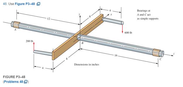
For Problems 48−50, draw the free-body diagram of the main shaft portion, labeled A, B, and C. Include any unbalanced torque on the shaft that tends to rotate it about the z-axis. In each case, the reaction to the unbalanced torque is taken at the right end of the shaft labeled C. Then draw the complete shearing force and bending moment diagrams for loading in the y−z plane. Also prepare a graph of the torque in the shaft as a function of position along the shaft from A to C.
Expert Solution & Answer
Want to see the full answer?
Check out a sample textbook solution
Students have asked these similar questions
Solve this problem and show all of the work
Solve this problem and show all of the work
Solve this problem and show all of the work
Chapter 3 Solutions
EBK MACHINE ELEMENTS IN MECHANICAL DESI
Ch. 3 - A tensile member in a machine structure is...Ch. 3 - Compute the stress in a round bar having a...Ch. 3 - Compute the stress in a rectangular bar having...Ch. 3 - A link in a packaging machine mechanism has a...Ch. 3 - Two circular rods support the 3800 lb weight of a...Ch. 3 - A tensile load of 5.00 kN is applied to a square...Ch. 3 - An aluminum rod is made in the form of a hollow...Ch. 3 - Compute the stress in the middle portion of rod AC...Ch. 3 - Compute the forces in the two angled rods in...Ch. 3 - If the rods from Problem 9 are circular, determine...
Ch. 3 - Repeat Problems 9 and 10 if the angle is 15 .Ch. 3 - Figure P312 shows a small truss spanning between...Ch. 3 - The truss shown in Figure P313 spans a total space...Ch. 3 - Figure P314 shows a short leg for a machine that...Ch. 3 - Consider the short compression member shown in...Ch. 3 - Refer Figure P38 . Each of the pins at A, B, and C...Ch. 3 - Compute the shear stress in the pins connecting...Ch. 3 - Prob. 18PCh. 3 - Prob. 19PCh. 3 - Prob. 20PCh. 3 - Prob. 21PCh. 3 - Compute the torsional shear stress in a circular...Ch. 3 - If the shaft of Problem 22 is 850 mm long and is...Ch. 3 - Compute the torsional shear stress due to a torque...Ch. 3 - Compute the torsional shear stress in a solid...Ch. 3 - Compute the torsional shear stress in a hollow...Ch. 3 - Compute the angle of twist for the hollow shaft of...Ch. 3 - A square steel bar, 25 mm on a side and 650 mm...Ch. 3 - A 3.00 in-diameter steel bar has a flat milled on...Ch. 3 - A commercial steel supplier lists rectangular...Ch. 3 - A beam is simply supported and carries the load...Ch. 3 - For each beam of Problem 31, compute its weight if...Ch. 3 - For each beam of Problem 31, compute the maximum...Ch. 3 - For the beam loading of Figure P334, draw the...Ch. 3 - For the beam loading of Figure P334, design the...Ch. 3 - Figure P336 shows a beam made from 4 in schedule...Ch. 3 - Select an aluminum I-beam shape to carry the load...Ch. 3 - Figure P338 represents a wood joist for a...Ch. 3 - For Problems 39 through 50, draw the free-body...Ch. 3 - Prob. 40PCh. 3 - For Problems 39 through 50, draw the free-body...Ch. 3 - Prob. 42PCh. 3 - Prob. 43PCh. 3 - Prob. 44PCh. 3 - For Problems 39 through 50, draw the free-body...Ch. 3 - For Problems 39 through 50, draw the free-body...Ch. 3 - For Problems 39 through 50, draw the free-body...Ch. 3 - For Problems 4850, draw the free-body diagram of...Ch. 3 - For Problems 4850, draw the free-body diagram of...Ch. 3 - Prob. 50PCh. 3 - Compute the maximum tensile stress in the bracket...Ch. 3 - Compute the maximum tensile and compressive...Ch. 3 - For the lever shown in Figure P353 (a), compute...Ch. 3 - Compute the maximum tensile stress at sections A...Ch. 3 - Prob. 55PCh. 3 - Refer to Figure P38. Compute the maximum tensile...Ch. 3 - Prob. 57PCh. 3 - Refer to P342. Compute the maximum stress in the...Ch. 3 - Refer to P343. Compute the maximum stress in the...Ch. 3 - Prob. 60PCh. 3 - Figure P361 shows a valve stem from an engine...Ch. 3 - The conveyor fixture shown in Figure P362 carries...Ch. 3 - For the flat plate in tension in Figure P363,...Ch. 3 - For Problems 64 through 68, compute the maximum...Ch. 3 - For Problems 64 through 68, compute the maximum...Ch. 3 - For Problems 64 through 68, compute the maximum...Ch. 3 - For Problems 64 through 68, compute the maximum...Ch. 3 - Prob. 68PCh. 3 - Figure P369 shows a horizontal beam supported by a...Ch. 3 - Prob. 70PCh. 3 - Prob. 71PCh. 3 - The beam shown in Figure P372 is a stepped, flat...Ch. 3 - Figure P373 shows a stepped, flat bar having a...Ch. 3 - Figure P374 shows a bracket carrying opposing...Ch. 3 - Prob. 75PCh. 3 - Figure P376 shows a lever made from a rectangular...Ch. 3 - For the lever in P376, determine the maximum...Ch. 3 - Figure P378 shows a shaft that is loaded only in...Ch. 3 - Prob. 79PCh. 3 - Prob. 80PCh. 3 - A hanger is made from ASTM A36 structural steel...Ch. 3 - A coping saw frame shown in Figure P382 is made...Ch. 3 - Prob. 83PCh. 3 - Figure P384 shows a hand garden tool used to break...Ch. 3 - Figure P385 shows a basketball backboard and goal...Ch. 3 - Prob. 86P
Knowledge Booster


Learn more about
Need a deep-dive on the concept behind this application? Look no further. Learn more about this topic, mechanical-engineering and related others by exploring similar questions and additional content below.Similar questions
- Please do not rely too much on chatgpt, because its answer may be wrong. Please consider it carefully and give your own answer. You can borrow ideas from gpt, but please do not believe its answer.Very very grateful! Please do not copy other's work,i will be very very grateful!!Please do not copy other's work,i will be very very grateful!!arrow_forward= The frame shown is fitted with three 50 cm diameter frictionless pulleys. A force of F = 630 N is applied to the rope at an angle ◊ 43°. Member ABCD is attached to the wall by a fixed support at A. Find the forces indicated below. Note: The rope is tangent to the pully (D) and not secured at the 3 o'clock position. a b •C *су G E e d BY NC SA 2013 Michael Swanbom Values for dimensions on the figure are given in the following table. Note the figure may not be to scale. Variable Value a 81 cm b 50 cm с 59 cm d 155 cm For all answers, take x as positive to the right and positive upward. At point A, the fixed support exerts a force of: A = + ĴN and a reaction couple of: →> ΜΑ Member CG is in Select an answer magnitude У as k N-m. and carries a force of N.arrow_forwardThe lower jaw AB [Purple 1] and the upper jaw-handle AD [Yellow 2] exert vertical clamping forces on the object at R. The hand squeezes the upper jaw-handle AD [2] and the lower handle BC [Orane 4] with forces F. (Member CD [Red 3] acts as if it is pinned at D, but, in a real vise-grips, its position is actually adjustable.) The clamping force, R, depends on the geometry and on the squeezing force F applied to the handles. Determine the proportionality between the clamping force, R, and the squeezing force F for the dimensions given. d3 d4 R 1 B d1 2 d2 D... d5 F 4 F Values for dimensions on the figure are given in the following table. Note the figure may not be to scale. Variable Value d1 65 mm d2 156 mm d3 50 mm 45 d4 d5 113 mm 30 mm R = Farrow_forward
- A triangular distributed load of max intensity w =460 N/m acts on beam AB. The beam is supported by a pin at A and member CD, which is connected by pins at C and D respectively. Determine the reaction forces at A and C. Enter your answers in Cartesian components. Assume the masses of both beam AB and member CD are negligible. cc 040 BY NC SA 2016 Eric Davishahl W A C D -a- B Ул -b- x Values for dimensions on the figure are given in the following table. Note the figure may not be to scale. Variable Value α 5.4 m b 8.64 m C 3.24 m The reaction at A is A = i+ ĴN. λ = i+ Ĵ N. The reaction at C is C =arrow_forward56 Clamps like the one shown are commonly used in woodworking applications. This clamp has the dimensions given in the table below the figure, and its jaws are mm thick (in the direction perpendicular to the plane of the picture). a.) The screws of the clamp are adjusted so that there is a uniform pressure of P = 150 kPa being applied to the workpieces by the jaws. Determine the force carried in each screw. Hint: the uniform pressure can be modeled in 2-D as a uniform distributed load with intensity w = Pt (units of N/m) acting over the length of contact between the jaw and the workpiece. b.) Determine the minimum vertical force (parallel to the jaws) required to pull either one of the workpieces out of the clamp jaws. Use a coefficient of static friction between all contacting surfaces of μs = 0.56 and the same clamping pressure given for part (a). 2013 Michael Swanbom A B C a Values for dimensions on the figure are given in the following table. Note the figure may not be to scale.…arrow_forwardDetermine the force in each member of the space truss given F=5 kN. Use positive to indicate tension and negative to indicate compression. F E Z -2 m. B 3 m C 5 m 3 m A -4 m. AB = KN FAC = FAD = KN KN KN FBC = KN FBD FBE = = KN Farrow_forward
- A short brass cyclinder (denisty=8530 kg/m^3, cp=0.389 kJ/kgK, k=110 W/mK, and alpha=3.39*10^-5 m^2/s) of diameter 4 cm and height 20 cm is initially at uniform temperature of 150 degrees C. The cylinder is now placed in atmospheric air at 20 degrees C, where heat transfer takes place by convection with a heat transfer coefficent of 40 W/m^2K. Calculate (a) the center temp of the cylinder, (b) the center temp of the top surface of the cylinder, and (c) the total heat transfer from the cylinder 15 min after the start of the cooling. Solve this problem using the analytical one term approximation method. (Answer: (a) 45.7C, (b)45.3C, (c)87.2 kJ)arrow_forwardA short brass cyclinder (denisty=8530 kg/m^3, cp=0.389 kJ/kgK, k=110 W/mK, and alpha=3.39*10^-5 m^2/s) of diameter 4 cm and height 20 cm is initially at uniform temperature of 150 degrees C. The cylinder is now placed in atmospheric air at 20 degrees C, where heat transfer takes place by convection with a heat transfer coefficent of 40 W/m^2K. Calculate (a) the center temp of the cylinder, (b) the center temp of the top surface of the cylinder, and (c) the total heat transfer from the cylinder 15 min after the start of the cooling. Solve this problem using the analytical one term approximation method.arrow_forwardA 6 cm high rectangular ice block (k=2.22 W/mK, and alpha=0.124*10^-7 m^2/s) initially at -18 degrees C is placed on a table on its square base 4 cm by 4cm in size in a room at 18 degrees C. The heat transfer coefficent on the exposed surfaces of the ice block is 12 W/m^2K. Disregarding any heat transfer from the base to the table, determine how long it will be before the ice block starts melting. Where on the ice block will the first liquid droplets appear? Solve this problem using the analytical one-term approximation method.arrow_forward
- Consider a piece of steel undergoing a decarburization process at 925 degrees C. the mass diffusivity of carbon in steel at 925 degrees C is 1*10^-7 cm^2/s. Determine the depth below the surface of the steel at which the concentration of carbon is reduced to 40 percent from its initial value as a result of the decarburization process for (a) an hour and (b) 10 hours. Assume the concnetration of carbon at the surface is zero throughout the decarburization process.arrow_forwardPlease do not rely too much on chatgpt, because its answer may be wrong. Please consider it carefully and give your own answer. You can borrow ideas from gpt, but please do not believe its answer.Very very grateful! Please do not copy other's work,i will be very very grateful!!arrow_forwardMultiple Choice Circle the best answer to each statement. 1. Which geometry attribute deviation(s) can be limited with a profile of a surface tolerance? A. Location B. Orientation C. Form D. All of the above 2. A true profile may be defined with: A. Basic radii B. Basic angles C. Formulas D. All of the above 3. Which modifier may be applied to the profile tolerance value? A B C. D. All of the above 4. The default tolerance zone for a profile tolerance is: A. Non-uniform B. Unilateral C. Bilateral equal distribution D. Bilateral-unequal distribution 5. An advantage of using a profile tolerance in place of a coordinate tolerance is: A. A bonus tolerance is permitted. B. A datum feature sequence may be specified C. A profile tolerance always controls size D. All of the above 6. The shape of the tolerance zone for a profile tolerance is: A. Two parallel planes B. The same as the true profile of the toleranced surface C. Equal bilateral D. Cylindrical when the diameter symbol is speci- fied…arrow_forward
arrow_back_ios
SEE MORE QUESTIONS
arrow_forward_ios
Recommended textbooks for you
 Mechanics of Materials (MindTap Course List)Mechanical EngineeringISBN:9781337093347Author:Barry J. Goodno, James M. GerePublisher:Cengage Learning
Mechanics of Materials (MindTap Course List)
Mechanical Engineering
ISBN:9781337093347
Author:Barry J. Goodno, James M. Gere
Publisher:Cengage Learning
Everything About TRANSVERSE SHEAR in 10 Minutes!! - Mechanics of Materials; Author: Less Boring Lectures;https://www.youtube.com/watch?v=4x0E9yvzfCM;License: Standard Youtube License