
Concept explainers
Videos
DATA You are
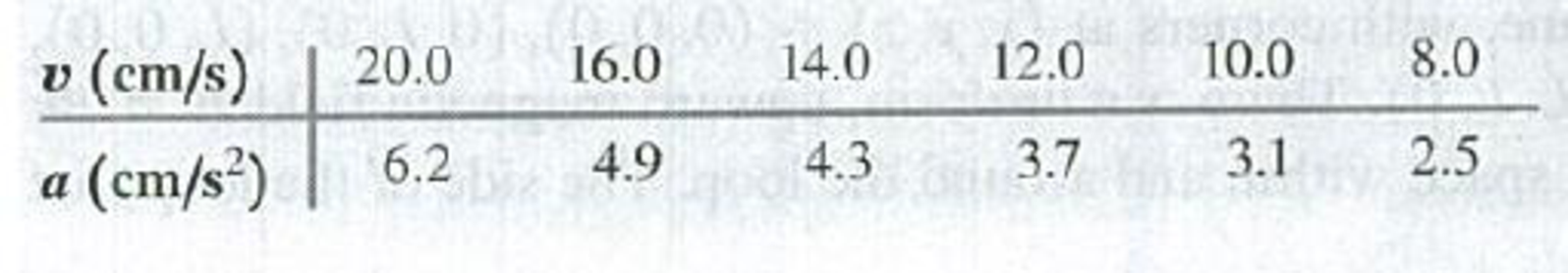
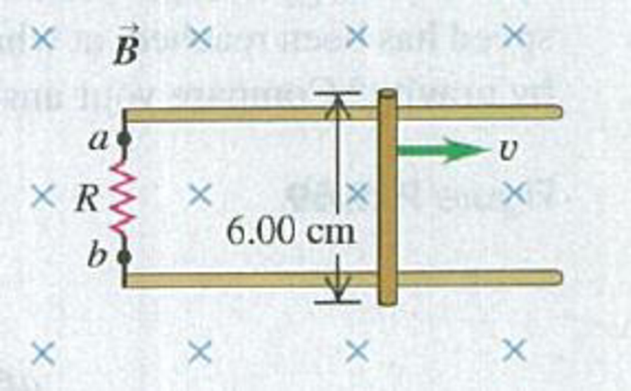
(a) Plot the data as a graph of a versus v. Explain why the data points plotted this way lie close to a straight line, and determine the slope of the best-fit straight line for the data. (b) Use your graph from part (a) to calculate the magnitude B of the magnetic field.(c) While the bar is moving, which end of the resistor, a or b, is at higher potential? (d) How many seconds does it take the speed of the bar to decrease from 20.0 cm/s to 10.0 cm/s?
Figure P29.67
Want to see the full answer?
Check out a sample textbook solution
Chapter 29 Solutions
University Physics (14th Edition)
Additional Science Textbook Solutions
College Physics
Essential University Physics (3rd Edition)
Essential University Physics: Volume 1 (3rd Edition)
Conceptual Integrated Science
College Physics: A Strategic Approach (3rd Edition)
The Cosmic Perspective (8th Edition)


- Q4: Show detailed work and pay attention to the units. There are two different ways to calculate the potential difference across the bar, using the motional EMF expression or Faraday's Law. Show that both methods give the same answer. Use the right hand rule to figure out which end of the bar (A or B) will be at a higher potential due to the motion of the conductor in the field.arrow_forwardA conducting rod slides on two parallel conducting bars as shown below. The bars are connected through a 10 ohm resistor which has a voltmeter attached across it. The bars are separated by .15m in the y direction. A force F is applied to therod to keep the rodmoving in the x direction at constant speed of v=6m/s. A uniform B-field of B=3mT is perpendicular to the x-y plane and points into the page as shown. R= 3mT とミ/Sm R= 10L IN a) Determine the magnetic flux D(x) as a function of x. b) Calculate d®/dt in Wb/s c) Determine the magnitude of EMF measured by the voltmeter. d) Calculate the current through the resistor and its direction (CW or CCW). e) Determine the magnitude of the force required to pull rod. f) Determine the energy density stored in the B-field.arrow_forwardA rail gun uses electromagnetic forces to accelerate a projectile to very high velocities. The basic mechanism of acceleration is relatively simple and can be illustrated in the following example. A metal rod of mass 40.0 g and electrical resistance 0.300 Ω rests on parallel horizontal rails that have negligible electric resistance. The rails are a distance L = 9.00 cm apart. (Figure 1)The rails are also connected to a voltage source providing a voltage of V = 5.00 V .The rod is placed in a vertical magnetic field. The rod begins to slide when the field reaches the value B = 0.131 T . Assume that the rod has a slightly flattened bottom so that it slides instead of rolling. Use 9.80 m/s^2 for the magnitude of the acceleration due to gravity. A) Find μ_s, the coefficient of static friction between the rod and the rails. Give the answer numericallyarrow_forward
- 6. Rail guns have been suggested for launching projectiles into space without chemical rockets. A tabletop model rail gun (Figure A2.4) consists of two long, parallel, horizontal rails, l= 3.50 cm apart, bridged by a bar of mass m= 3.00 g that is free to slide without friction. The rails and bar have low electric resistance, and the current is limited to a constant I = 24.0 A by a power supply that is far to the left of the figure, so it has no magnetic effect on the bar. Figure A2.4 shows the bar at rest at the midpoint of the rails at the moment the current is established. We wish to find the speed with which the bar leaves the rails after being released from the midpoint of the rails. (a) Find the magnitude of the magnetic field at a distance of 1.75 cm from a single long wire carrying a current of 2.40 A. (b) For purposes of evaluating the magnetic field, model the rails as infinitely long. Using the result of part (a), find the magnitude and direction of the magnetic field at the…arrow_forwardA resistor R is connected between two parallel conducting rails separated by 30 cm, as shown in the diagram. A conducting bar maintains electric contact with the rails as it moves relative to them with constant velocity from x = 20 cm to x = 48 cm in 0.6 seconds. A uniform 0.8 T field points into the page. Calculate the induced electric potential difference between the two ends of the bar.arrow_forwardA current - carrying rectangular wire loop with width a = 0.120 mand length b = 0.200 m is in the xy - plane, supported by a nonconducting,frictionless axle of negligible weight. A current of I = 3.00 A travels counterclockwise in the circuit (Fig. P19.38).Calculate the magnitude and direction of the force exerted onthe (a) left and (b) right segments of wire by a uniform magneticfield of 0.250 T that points in the positive x - direction.Find the magnetic force exerted on the (c) top and (d) bottomsegments. (e) Find the magnitude of the net torque on the loopabout the axle.arrow_forward
- A portion of a long, cylindrical coaxial cable is shown in the figure below. An electrical current I = 3.0 amps flows down the center conductor, and this same current is returned in the outer conductor. Assume the current is distributed uniformly over the cross sections of the two parts of the cable. The values of the radii in the figure are r1 = 1.5 mm, r2 = 4.0 mm, and r3 = 7.0 mm. Using Ampere’s Law, find the magnitude of the magnetic field at the following distances from the center of the inner wire: a. 1.0 mm. b. 3.0 mm. c. 5.5 mm. d. 9.0 mm.arrow_forwardTwo long straight wires enter a room through a door. One carries a current of 3.0 A into the room while the other carries a current of 5.0 A out. What is the magnitude of the path integral $B ds around the door frame? O 6.3 x 10⁻⁶ T-m O 2.5 x 10⁻⁶ T-m O 3.8 x 10⁻⁶ T-m O None of these O 1.0 x 10⁻⁶ T-marrow_forwardThe figure below is a cross-sectional view of a coaxial cable. The center conductor is surrounded by a rubber layer, an outer conductor, and another rubber layer. In a particular application, the current in the inner conductor is I₁ = 1.20 A out of the page and the current in the outer conductor is I2 = 2.96 A into the page. Assuming the distance d = 1.00 mm, answer the following. I X 1₂ (a) Determine the magnitude and direction of the magnetic field at point a. magnitude μT direction to the left (b) Determine the magnitude and direction of the magnetic field at point b. μT magnitude direction into the pagearrow_forward
- Consider a coaxial cable as shown in the figure. The cable consists of a solid inner conductor of radius ri = 0.4 cm that is surrounded by a cylindrical tube of inner radius r2 0.8 cm and outer radius r3 = 1.8 cm. The conductors carry equal and opposite currents I = 1 A but the current density varies linearly with the distance from the center for the inner conductor (j1 C1r) while it is distributed uniformly for the outer conductor. Determine the magnetic field (in units of uT (microtesla)) at a distance r 1.3 cm from the axis. = 47 x 10-7 N/A? and T = 3.14) Answerarrow_forwardA biophysics experiment uses a very sensitive magnetic field probe to determine the current associated with a nerve impulse traveling along an axon. If the peak field strength 1.0 mm from an axon is 8.0 pT, what is the peak current carried by the axon?arrow_forwardTwo very long, parallel wires are separated by d = 0.065 m. The first wire carries a current of I1 = 0.75 A. The second wire carries a current of I2 = 0.65 A. Express the minimal work per unit length needed to separate the two wires from d to 2d.arrow_forward
 Principles of Physics: A Calculus-Based TextPhysicsISBN:9781133104261Author:Raymond A. Serway, John W. JewettPublisher:Cengage Learning
 Physics for Scientists and Engineers: Foundations...PhysicsISBN:9781133939146Author:Katz, Debora M.Publisher:Cengage Learning