EP MODIFIED MASTERING ENGINEERING WITH
14th Edition
ISBN: 9780133941357
Author: HIBBELER
Publisher: PEARSON CO
expand_more
expand_more
format_list_bulleted
Concept explainers
Videos
Textbook Question
Chapter 2.9, Problem 113P
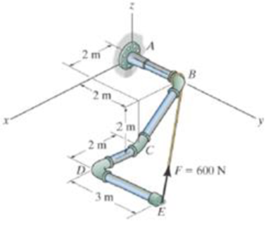
Determine the magnitudes of the components of F = 600 N acting along and perpendicular to segment DE of the pipe assembly.
Expert Solution & Answer

Trending nowThis is a popular solution!

Students have asked these similar questions
Quick solution required.
My request, Don't use Ai.
Mechanical engineering
Please give handwritten solution, don't use chatgpt.
Fbd should be included
(I) [40 Points] Using centered finite difference approximations as done in class, solve the equation for O:
d20
dx²
+ 0.010+ Q=0
subject to the boundary conditions shown in the stencil below. Do this for two values of Q: (a) Q = 0.3,
and (b) Q= √(0.5 + 2x)e-sinx (cos(5x)+x-0.5√1.006-x| + e −43*|1+.001+x* | * sin (1.5 − x) +
(cosx+0.001 + ex-1250+ sin (1-0.9x)|) * x - 4.68x4. For Case (a) (that is, Q = 0.3), use the stencil in Fig.
1. For Case (b), calculate with both the stencils in Fig. 1 and Fig 2. For all the three cases, show a table as
well as a plot of O versus x. Discuss your results. Use MATLAB and hand in the MATLAB codes.
1
0=0
x=0
2
3
4
0=1
x=1
Fig 1
1 2 3 4 5 6 7 8 9 10
11
0=0
x=0
0=1
x=1
Fig 2
Chapter 2 Solutions
EP MODIFIED MASTERING ENGINEERING WITH
Ch. 2.3 - In each case, construct the parallelogram law to...Ch. 2.3 - In each case, show how to resolve the force F into...Ch. 2.3 - Determine the magnitude of the resultant force...Ch. 2.3 - Two forces act on the hook. Determine the...Ch. 2.3 - Determine the magnitude of the resultant force and...Ch. 2.3 - Resolve the 30-lb force into components along the...Ch. 2.3 - The force F = 450 lb acts on the frame. Resolve...Ch. 2.3 - If force F is to have a component along the u axis...Ch. 2.3 - If = 60 and F = 450 N, determine the magnitude of...Ch. 2.3 - If the magnitude of the resultant force is to be...
Ch. 2.3 - Determine the magnitude of the resultant force FR...Ch. 2.3 - The vertical force F acts downward at A on the...Ch. 2.3 - Solve with F = 350 lb. Prob. 2-4/5Ch. 2.3 - Determine the magnitude of the resultant force FR...Ch. 2.3 - Resolve the force F1 into components acting along...Ch. 2.3 - Resolve the force F2 into components acting along...Ch. 2.3 - If the resultant force acting on the support is to...Ch. 2.3 - Determine the magnitude of the resultant force and...Ch. 2.3 - The plate is subjected to the two forces at A and...Ch. 2.3 - Determine the angle for connecting member A to...Ch. 2.3 - The force acting on the gear tooth is F = 20lb....Ch. 2.3 - The component of force F acting along line aa is...Ch. 2.3 - Force F acts on the frame such that its component...Ch. 2.3 - Force F acts on the frame such that its component...Ch. 2.3 - Determine the magnitude and direction of the...Ch. 2.3 - Determine the magnitude and direction of the...Ch. 2.3 - Determine the design angle (0 90) for strut AB...Ch. 2.3 - Determine the design angle (0 90) between...Ch. 2.3 - Determine the magnitude and direction of the...Ch. 2.3 - Prob. 22PCh. 2.3 - Prob. 23PCh. 2.3 - Prob. 24PCh. 2.3 - If F1 = 30 lb and F2 = 40 lb, determine the angles...Ch. 2.3 - Determine the magnitude and direction of FA SO...Ch. 2.3 - Determine the magnitude and direction, measured...Ch. 2.3 - Determine the magnitude of force F so that the...Ch. 2.3 - If the resultant force of the two tugboats is 3...Ch. 2.3 - If FB = 3 kN and = 45, determine the magnitude of...Ch. 2.3 - If the resultant force of the two tugboats is...Ch. 2.4 - Resolve each force acting on the post into its x...Ch. 2.4 - Determine the magnitude and direction of the...Ch. 2.4 - Prob. 9FPCh. 2.4 - If the resultant force acting on the bracket is to...Ch. 2.4 - If the magnitude of the resultant force acting on...Ch. 2.4 - Determine the magnitude of the resultant force and...Ch. 2.4 - Determine the magnitude of the resultant force and...Ch. 2.4 - Prob. 33PCh. 2.4 - Prob. 34PCh. 2.4 - Determine the magnitude of the resultant force and...Ch. 2.4 - Resolve each force acting on the gusset plate into...Ch. 2.4 - Determine the magnitude of the resultant force...Ch. 2.4 - Prob. 38PCh. 2.4 - Prob. 39PCh. 2.4 - Determine the magnitude of the resultant force and...Ch. 2.4 - Determine the magnitude of the resultant force and...Ch. 2.4 - Express F1, F2, and F3 as Cartesian vectors.Ch. 2.4 - Prob. 43PCh. 2.4 - Prob. 44PCh. 2.4 - Prob. 45PCh. 2.4 - Determine the magnitude and orientation of FB so...Ch. 2.4 - Determine the magnitude and orientation. measured...Ch. 2.4 - Prob. 48PCh. 2.4 - Prob. 49PCh. 2.4 - Express F1, F2, and F3 as Cartesian vectors.Ch. 2.4 - Prob. 51PCh. 2.4 - Prob. 52PCh. 2.4 - Prob. 53PCh. 2.4 - Prob. 54PCh. 2.4 - Prob. 55PCh. 2.4 - Prob. 56PCh. 2.4 - If the resultant force acting on the bracket is...Ch. 2.4 - Prob. 58PCh. 2.4 - If F = 5 kN and = 30, determine the magnitude of...Ch. 2.6 - Sketch the following forces on the x, y, z...Ch. 2.6 - In each case, establish F as a Cartesian vector,...Ch. 2.6 - Show how to resolve each force into its x, y, z...Ch. 2.6 - Determine the coordinate direction angles of the...Ch. 2.6 - Prob. 14FPCh. 2.6 - Prob. 15FPCh. 2.6 - Prob. 16FPCh. 2.6 - Prob. 17FPCh. 2.6 - Prob. 18FPCh. 2.6 - The force F has a magnitude of 80 lb and acts...Ch. 2.6 - Prob. 61PCh. 2.6 - Prob. 62PCh. 2.6 - Prob. 63PCh. 2.6 - Prob. 64PCh. 2.6 - The screw eye is subjected to the two forces...Ch. 2.6 - Prob. 66PCh. 2.6 - Determine the magnitude and coordinate direction...Ch. 2.6 - Determine the magnitude and coordinate direction...Ch. 2.6 - Determine the magnitude and coordinate direction...Ch. 2.6 - Determine the magnitude and coordinate direction...Ch. 2.6 - Specify the magnitude and coordinate direction...Ch. 2.6 - Prob. 72PCh. 2.6 - Prob. 73PCh. 2.6 - Prob. 74PCh. 2.6 - Prob. 75PCh. 2.6 - Prob. 76PCh. 2.6 - Prob. 77PCh. 2.6 - Prob. 78PCh. 2.6 - Determine the coordinate direction angles of the...Ch. 2.6 - The bracket is subjected to the two forces shown....Ch. 2.6 - Prob. 81PCh. 2.6 - Prob. 82PCh. 2.6 - If the direction of the resultant force acting on...Ch. 2.6 - Prob. 84PCh. 2.6 - The pole is subjected to the force F which has...Ch. 2.8 - In each case, establish a position vector from...Ch. 2.8 - In each case, express F as a Cartesian vector....Ch. 2.8 - Express the position vector rAB in Cartesian...Ch. 2.8 - Prob. 20FPCh. 2.8 - Express the force as a Cartesian vector. Prob....Ch. 2.8 - Prob. 22FPCh. 2.8 - Prob. 23FPCh. 2.8 - Prob. 24FPCh. 2.8 - Determine the length of the connecting rod AB by...Ch. 2.8 - Express force F as a Cartesian vector; then...Ch. 2.8 - Prob. 88PCh. 2.8 - Prob. 89PCh. 2.8 - Prob. 90PCh. 2.8 - Prob. 91PCh. 2.8 - Prob. 92PCh. 2.8 - If FB = 560 N and FC = 700 N, determine the...Ch. 2.8 - If FB = 700 N, and FC = 560 N, determine the...Ch. 2.8 - The plate is suspended using the three cables...Ch. 2.8 - The three supporting cables exert the forces shown...Ch. 2.8 - Determine the magnitude and coordinate direction...Ch. 2.8 - Prob. 98PCh. 2.8 - Prob. 99PCh. 2.8 - Prob. 100PCh. 2.8 - The two mooring cables exert forces on the stern...Ch. 2.8 - Prob. 102PCh. 2.8 - Determine the magnitude and coordinate direction...Ch. 2.8 - If the force in each cable tied to the bin is 70...Ch. 2.8 - If the resultant of the four forces is FR = {360k}...Ch. 2.9 - P2.8. in each case set up the dot product to find...Ch. 2.9 - Prob. 9PPCh. 2.9 - Prob. 25FPCh. 2.9 - Determine the angle between the force and the...Ch. 2.9 - Prob. 27FPCh. 2.9 - Prob. 28FPCh. 2.9 - Find the magnitude of the projected component of...Ch. 2.9 - Prob. 30FPCh. 2.9 - Determine the magnitudes of the components of the...Ch. 2.9 - Prob. 106PCh. 2.9 - Prob. 107PCh. 2.9 - Prob. 108PCh. 2.9 - Prob. 109PCh. 2.9 - Prob. 110PCh. 2.9 - Prob. 111PCh. 2.9 - Prob. 112PCh. 2.9 - Determine the magnitudes of the components of F =...Ch. 2.9 - Prob. 114PCh. 2.9 - Prob. 115PCh. 2.9 - Prob. 116PCh. 2.9 - Determine the magnitudes of the projected...Ch. 2.9 - Determine the angle between cables AB and AC....Ch. 2.9 - Prob. 119PCh. 2.9 - Prob. 120PCh. 2.9 - Determine the angle between the two cables...Ch. 2.9 - Determine the angle between the cables AB and AC....Ch. 2.9 - Determine the magnitude of the projected component...Ch. 2.9 - Determine the magnitude of the projected component...Ch. 2.9 - Determine the magnitude of the projection of force...Ch. 2.9 - Prob. 126PCh. 2.9 - Prob. 127PCh. 2.9 - Prob. 128PCh. 2.9 - Determine the magnitude of the projected component...Ch. 2.9 - Prob. 130PCh. 2.9 - Prob. 131PCh. 2.9 - Determine the magnitude of the projected component...Ch. 2.9 - Prob. 133PCh. 2.9 - Prob. 134PCh. 2.9 - Prob. 135PCh. 2.9 - Prob. 136PCh. 2.9 - Prob. 137PCh. 2.9 - Prob. 138PCh. 2.9 - Prob. 139PCh. 2.9 - Determine the magnitude of the resultant force FR...Ch. 2.9 - Resolve F into components along the u and v axes...Ch. 2.9 - Prob. 3RPCh. 2.9 - The cable at the end of the crane boom exerts a...Ch. 2.9 - Prob. 5RPCh. 2.9 - Prob. 6RPCh. 2.9 - Prob. 7RPCh. 2.9 - Prob. 8RP
Knowledge Booster


Learn more about
Need a deep-dive on the concept behind this application? Look no further. Learn more about this topic, mechanical-engineering and related others by exploring similar questions and additional content below.Similar questions
- Fig 2 (II) [60 Points] Using centered finite difference approximation as done in class, solve the equation: 020 020 + მx2 მy2 +0.0150+Q=0 subject to the boundary conditions shown in the stencils below. Do this for two values of Q: (a) Q = 0.3, and (b) Q = 10.5x² + 1.26 * 1.5 x 0.002 0.008. For Case (a) (that is, Q = 0.3) use Fig 3. For Case (b), use both Fig. 3 and Fig 4. For all the three cases, show a table as well as the contour plots of versus (x, y), and the (x, y) heat flux values at all the nodes on the boundaries x = 1 and y = 1. Discuss your results. Use MATLAB and hand in the MATLAB codes. (Note that the domain is (x, y)e[0,1] x [0,1].) 0=0 0=0 4 8 12 16 10 Ꮎ0 15 25 9 14 19 24 3 11 15 0=0 8-0 0=0 3 8 13 18 23 2 6 сл 5 0=0 10 14 6 12 17 22 1 6 11 16 21 13 e=0 Fig 3 Fig 4 Textbook: Numerical Methods for Engineers, Steven C. Chapra and Raymond P. Canale, McGraw-Hill, Eighth Edition (2021).arrow_forwardShip construction question. Sketch and describe the forward arrangements of a ship. Include componets of the structure and a explanation of each part/ term. Ive attached a general fore end arrangement. Simplfy construction and give a brief describion of the terms.arrow_forwardProblem 1 Consider R has a functional relationship with variables in the form R = K xq xx using show that n ✓ - (OR 1.) = i=1 2 Их Ux2 Ихэ 2 (177)² = ² (1)² + b² (12)² + c² (1)² 2 UR R x2 x3arrow_forward
- 4. Figure 3 shows a crank loaded by a force F = 1000 N and Mx = 40 Nm. a. Draw a free-body diagram of arm 2 showing the values of all forces, moments, and torques that act due to force F. Label the directions of the coordinate axes on this diagram. b. Draw a free-body diagram of arm 2 showing the values of all forces, moments, and torques that act due to moment Mr. Label the directions of the coordinate axes on this diagram. Draw a free body diagram of the wall plane showing all the forces, torques, and moments acting there. d. Locate a stress element on the top surface of the shaft at A and calculate all the stress components that act upon this element. e. Determine the principal stresses and maximum shear stresses at this point at A.arrow_forward3. Given a heat treated 6061 aluminum, solid, elliptical column with 200 mm length, 200 N concentric load, and a safety factor of 1.2, design a suitable column if its boundary conditions are fixed-free and the ratio of major to minor axis is 2.5:1. (Use AISC recommended values and round the ellipse dimensions so that both axes are whole millimeters in the correct 2.5:1 ratio.)arrow_forward1. A simply supported shaft is shown in Figure 1 with w₁ = 25 N/cm and M = 20 N cm. Use singularity functions to determine the reactions at the supports. Assume El = 1000 kN cm². Wo M 0 10 20 30 40 50 60 70 80 90 100 110 cm Figure 1 - Problem 1arrow_forward
- Please AnswerSteam enters a nozzle at 400°C and 800 kPa with a velocity of 10 m/s and leaves at 375°C and 400 kPa while losing heat at a rate of 26.5 kW. For an inlet area of 800 cm2, determine the velocity and the volume flow rate of the steam at the nozzle exit. Use steam tables. The velocity of the steam at the nozzle exit is m/s. The volume flow rate of the steam at the nozzle exit is m3/s.arrow_forward2. A support hook was formed from a rectangular bar. Find the stresses at the inner and outer surfaces at sections just above and just below O-B. -210 mm 120 mm 160 mm 400 N B thickness 8 mm = Figure 2 - Problem 2arrow_forwardSteam flows steadily through a turbine at a rate of 45,000 lbm/h, entering at 1000 psia and 900°F and leaving at 5 psia as saturated vapor. If the power generated by the turbine is 4.1 MW, determine the rate of heat loss from the steam. The enthalpies are h1 = 1448.6 Btu/lbm and h2 = 1130.7 Btu/lbm. The rate of heat loss from the steam is Btu/s.arrow_forward
- The A/D converter wit the specifications listed below is planned to be used in an environment in which the A/D converter temperature may change by ± 10 °C. Estimate the contributions of conversion and quantization errors to the uncertainty in the digital representation of an analog voltage by the converter. FSO N Linearity error Temperature drift error Analog to Digital (A/D) Converter 0-10 V 12 bits ± 3 bits 1 bit/5 °Carrow_forward6-13. A smooth tube in the form of a circle of radius r rotates in its vertical plane with a constant angular velocity w. The position of a particle of mass m that slides inside the tube is given by the relative coordinate p. Find the differential equation for . e О E g ω Figure P6-13arrow_forwardProblem 2 Consider the power drawn by a resistance load in a DC circuit. The power is calculated as P = VI or P = 1²R. It is given that the normalized uncertainty or % percentage uncertainty in measurements of I, R, and V are the same. Find the uncertainty in P using the two different expressions for power. Is the uncertainty using the two methods the same? If not, WHY, explain?arrow_forward
arrow_back_ios
SEE MORE QUESTIONS
arrow_forward_ios
Recommended textbooks for you
 International Edition---engineering Mechanics: St...Mechanical EngineeringISBN:9781305501607Author:Andrew Pytel And Jaan KiusalaasPublisher:CENGAGE L
International Edition---engineering Mechanics: St...
Mechanical Engineering
ISBN:9781305501607
Author:Andrew Pytel And Jaan Kiusalaas
Publisher:CENGAGE L
Types Of loads - Engineering Mechanics | Abhishek Explained; Author: Prime Course;https://www.youtube.com/watch?v=4JVoL9wb5yM;License: Standard YouTube License, CC-BY