EP MODIFIED MASTERING ENGINEERING WITH
14th Edition
ISBN: 9780133941357
Author: HIBBELER
Publisher: PEARSON CO
expand_more
expand_more
format_list_bulleted
Videos
Textbook Question
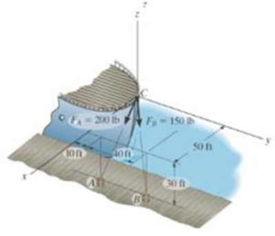
Chapter 2.8, Problem 101P
The two mooring cables exert forces on the stern of a ship as shown. Represent each force as a Cartesian
Expert Solution & Answer
Want to see the full answer?
Check out a sample textbook solution
Students have asked these similar questions
A thin uniform rod of mass m and length 2r rests in a smooth hemispherical bowl of radius r. A
moment M
=
mgr
horizontal plane.
is applied to the rod. Assume that the bowl is fixed and its rim is in the
HINT: It will help you to find the length l of that portion of the rod that remains outside the
bowl.
M
2r
Ꮎ
a) How many degrees of freedom does this system have?
b) Write an equation for the virtual work in terms of the angle 0 and the motion of the
center of mass (TF)
c) Derive an equation for the variation in the position of the center of mass (i.e., Sŕƒ)
a. HINT: Use the center of the bowl as the coordinate system origin for the problem.
d) In the case of no applied moment (i.e., M = 0), derive an equation that can be used to
solve for the equilibrium angle of the rod. DO NOT solve the equation
e) In the case of an applied moment (i.e., M:
=
mgr
4
-) derive an equation that can be used to
solve for the equilibrium angle of the rod. DO NOT solve the equation.
f) Can the angle 0 and…
Solve this problem and show all of the work
Solve this problem and show all of the work
Chapter 2 Solutions
EP MODIFIED MASTERING ENGINEERING WITH
Ch. 2.3 - In each case, construct the parallelogram law to...Ch. 2.3 - In each case, show how to resolve the force F into...Ch. 2.3 - Determine the magnitude of the resultant force...Ch. 2.3 - Two forces act on the hook. Determine the...Ch. 2.3 - Determine the magnitude of the resultant force and...Ch. 2.3 - Resolve the 30-lb force into components along the...Ch. 2.3 - The force F = 450 lb acts on the frame. Resolve...Ch. 2.3 - If force F is to have a component along the u axis...Ch. 2.3 - If = 60 and F = 450 N, determine the magnitude of...Ch. 2.3 - If the magnitude of the resultant force is to be...
Ch. 2.3 - Determine the magnitude of the resultant force FR...Ch. 2.3 - The vertical force F acts downward at A on the...Ch. 2.3 - Solve with F = 350 lb. Prob. 2-4/5Ch. 2.3 - Determine the magnitude of the resultant force FR...Ch. 2.3 - Resolve the force F1 into components acting along...Ch. 2.3 - Resolve the force F2 into components acting along...Ch. 2.3 - If the resultant force acting on the support is to...Ch. 2.3 - Determine the magnitude of the resultant force and...Ch. 2.3 - The plate is subjected to the two forces at A and...Ch. 2.3 - Determine the angle for connecting member A to...Ch. 2.3 - The force acting on the gear tooth is F = 20lb....Ch. 2.3 - The component of force F acting along line aa is...Ch. 2.3 - Force F acts on the frame such that its component...Ch. 2.3 - Force F acts on the frame such that its component...Ch. 2.3 - Determine the magnitude and direction of the...Ch. 2.3 - Determine the magnitude and direction of the...Ch. 2.3 - Determine the design angle (0 90) for strut AB...Ch. 2.3 - Determine the design angle (0 90) between...Ch. 2.3 - Determine the magnitude and direction of the...Ch. 2.3 - Prob. 22PCh. 2.3 - Prob. 23PCh. 2.3 - Prob. 24PCh. 2.3 - If F1 = 30 lb and F2 = 40 lb, determine the angles...Ch. 2.3 - Determine the magnitude and direction of FA SO...Ch. 2.3 - Determine the magnitude and direction, measured...Ch. 2.3 - Determine the magnitude of force F so that the...Ch. 2.3 - If the resultant force of the two tugboats is 3...Ch. 2.3 - If FB = 3 kN and = 45, determine the magnitude of...Ch. 2.3 - If the resultant force of the two tugboats is...Ch. 2.4 - Resolve each force acting on the post into its x...Ch. 2.4 - Determine the magnitude and direction of the...Ch. 2.4 - Prob. 9FPCh. 2.4 - If the resultant force acting on the bracket is to...Ch. 2.4 - If the magnitude of the resultant force acting on...Ch. 2.4 - Determine the magnitude of the resultant force and...Ch. 2.4 - Determine the magnitude of the resultant force and...Ch. 2.4 - Prob. 33PCh. 2.4 - Prob. 34PCh. 2.4 - Determine the magnitude of the resultant force and...Ch. 2.4 - Resolve each force acting on the gusset plate into...Ch. 2.4 - Determine the magnitude of the resultant force...Ch. 2.4 - Prob. 38PCh. 2.4 - Prob. 39PCh. 2.4 - Determine the magnitude of the resultant force and...Ch. 2.4 - Determine the magnitude of the resultant force and...Ch. 2.4 - Express F1, F2, and F3 as Cartesian vectors.Ch. 2.4 - Prob. 43PCh. 2.4 - Prob. 44PCh. 2.4 - Prob. 45PCh. 2.4 - Determine the magnitude and orientation of FB so...Ch. 2.4 - Determine the magnitude and orientation. measured...Ch. 2.4 - Prob. 48PCh. 2.4 - Prob. 49PCh. 2.4 - Express F1, F2, and F3 as Cartesian vectors.Ch. 2.4 - Prob. 51PCh. 2.4 - Prob. 52PCh. 2.4 - Prob. 53PCh. 2.4 - Prob. 54PCh. 2.4 - Prob. 55PCh. 2.4 - Prob. 56PCh. 2.4 - If the resultant force acting on the bracket is...Ch. 2.4 - Prob. 58PCh. 2.4 - If F = 5 kN and = 30, determine the magnitude of...Ch. 2.6 - Sketch the following forces on the x, y, z...Ch. 2.6 - In each case, establish F as a Cartesian vector,...Ch. 2.6 - Show how to resolve each force into its x, y, z...Ch. 2.6 - Determine the coordinate direction angles of the...Ch. 2.6 - Prob. 14FPCh. 2.6 - Prob. 15FPCh. 2.6 - Prob. 16FPCh. 2.6 - Prob. 17FPCh. 2.6 - Prob. 18FPCh. 2.6 - The force F has a magnitude of 80 lb and acts...Ch. 2.6 - Prob. 61PCh. 2.6 - Prob. 62PCh. 2.6 - Prob. 63PCh. 2.6 - Prob. 64PCh. 2.6 - The screw eye is subjected to the two forces...Ch. 2.6 - Prob. 66PCh. 2.6 - Determine the magnitude and coordinate direction...Ch. 2.6 - Determine the magnitude and coordinate direction...Ch. 2.6 - Determine the magnitude and coordinate direction...Ch. 2.6 - Determine the magnitude and coordinate direction...Ch. 2.6 - Specify the magnitude and coordinate direction...Ch. 2.6 - Prob. 72PCh. 2.6 - Prob. 73PCh. 2.6 - Prob. 74PCh. 2.6 - Prob. 75PCh. 2.6 - Prob. 76PCh. 2.6 - Prob. 77PCh. 2.6 - Prob. 78PCh. 2.6 - Determine the coordinate direction angles of the...Ch. 2.6 - The bracket is subjected to the two forces shown....Ch. 2.6 - Prob. 81PCh. 2.6 - Prob. 82PCh. 2.6 - If the direction of the resultant force acting on...Ch. 2.6 - Prob. 84PCh. 2.6 - The pole is subjected to the force F which has...Ch. 2.8 - In each case, establish a position vector from...Ch. 2.8 - In each case, express F as a Cartesian vector....Ch. 2.8 - Express the position vector rAB in Cartesian...Ch. 2.8 - Prob. 20FPCh. 2.8 - Express the force as a Cartesian vector. Prob....Ch. 2.8 - Prob. 22FPCh. 2.8 - Prob. 23FPCh. 2.8 - Prob. 24FPCh. 2.8 - Determine the length of the connecting rod AB by...Ch. 2.8 - Express force F as a Cartesian vector; then...Ch. 2.8 - Prob. 88PCh. 2.8 - Prob. 89PCh. 2.8 - Prob. 90PCh. 2.8 - Prob. 91PCh. 2.8 - Prob. 92PCh. 2.8 - If FB = 560 N and FC = 700 N, determine the...Ch. 2.8 - If FB = 700 N, and FC = 560 N, determine the...Ch. 2.8 - The plate is suspended using the three cables...Ch. 2.8 - The three supporting cables exert the forces shown...Ch. 2.8 - Determine the magnitude and coordinate direction...Ch. 2.8 - Prob. 98PCh. 2.8 - Prob. 99PCh. 2.8 - Prob. 100PCh. 2.8 - The two mooring cables exert forces on the stern...Ch. 2.8 - Prob. 102PCh. 2.8 - Determine the magnitude and coordinate direction...Ch. 2.8 - If the force in each cable tied to the bin is 70...Ch. 2.8 - If the resultant of the four forces is FR = {360k}...Ch. 2.9 - P2.8. in each case set up the dot product to find...Ch. 2.9 - Prob. 9PPCh. 2.9 - Prob. 25FPCh. 2.9 - Determine the angle between the force and the...Ch. 2.9 - Prob. 27FPCh. 2.9 - Prob. 28FPCh. 2.9 - Find the magnitude of the projected component of...Ch. 2.9 - Prob. 30FPCh. 2.9 - Determine the magnitudes of the components of the...Ch. 2.9 - Prob. 106PCh. 2.9 - Prob. 107PCh. 2.9 - Prob. 108PCh. 2.9 - Prob. 109PCh. 2.9 - Prob. 110PCh. 2.9 - Prob. 111PCh. 2.9 - Prob. 112PCh. 2.9 - Determine the magnitudes of the components of F =...Ch. 2.9 - Prob. 114PCh. 2.9 - Prob. 115PCh. 2.9 - Prob. 116PCh. 2.9 - Determine the magnitudes of the projected...Ch. 2.9 - Determine the angle between cables AB and AC....Ch. 2.9 - Prob. 119PCh. 2.9 - Prob. 120PCh. 2.9 - Determine the angle between the two cables...Ch. 2.9 - Determine the angle between the cables AB and AC....Ch. 2.9 - Determine the magnitude of the projected component...Ch. 2.9 - Determine the magnitude of the projected component...Ch. 2.9 - Determine the magnitude of the projection of force...Ch. 2.9 - Prob. 126PCh. 2.9 - Prob. 127PCh. 2.9 - Prob. 128PCh. 2.9 - Determine the magnitude of the projected component...Ch. 2.9 - Prob. 130PCh. 2.9 - Prob. 131PCh. 2.9 - Determine the magnitude of the projected component...Ch. 2.9 - Prob. 133PCh. 2.9 - Prob. 134PCh. 2.9 - Prob. 135PCh. 2.9 - Prob. 136PCh. 2.9 - Prob. 137PCh. 2.9 - Prob. 138PCh. 2.9 - Prob. 139PCh. 2.9 - Determine the magnitude of the resultant force FR...Ch. 2.9 - Resolve F into components along the u and v axes...Ch. 2.9 - Prob. 3RPCh. 2.9 - The cable at the end of the crane boom exerts a...Ch. 2.9 - Prob. 5RPCh. 2.9 - Prob. 6RPCh. 2.9 - Prob. 7RPCh. 2.9 - Prob. 8RP
Knowledge Booster


Learn more about
Need a deep-dive on the concept behind this application? Look no further. Learn more about this topic, mechanical-engineering and related others by exploring similar questions and additional content below.Similar questions
- Solve this problem and show all of the workarrow_forwardPlease do not rely too much on chatgpt, because its answer may be wrong. Please consider it carefully and give your own answer. You can borrow ideas from gpt, but please do not believe its answer.Very very grateful! Please do not copy other's work,i will be very very grateful!!Please do not copy other's work,i will be very very grateful!!arrow_forward= The frame shown is fitted with three 50 cm diameter frictionless pulleys. A force of F = 630 N is applied to the rope at an angle ◊ 43°. Member ABCD is attached to the wall by a fixed support at A. Find the forces indicated below. Note: The rope is tangent to the pully (D) and not secured at the 3 o'clock position. a b •C *су G E e d BY NC SA 2013 Michael Swanbom Values for dimensions on the figure are given in the following table. Note the figure may not be to scale. Variable Value a 81 cm b 50 cm с 59 cm d 155 cm For all answers, take x as positive to the right and positive upward. At point A, the fixed support exerts a force of: A = + ĴN and a reaction couple of: →> ΜΑ Member CG is in Select an answer magnitude У as k N-m. and carries a force of N.arrow_forward
- The lower jaw AB [Purple 1] and the upper jaw-handle AD [Yellow 2] exert vertical clamping forces on the object at R. The hand squeezes the upper jaw-handle AD [2] and the lower handle BC [Orane 4] with forces F. (Member CD [Red 3] acts as if it is pinned at D, but, in a real vise-grips, its position is actually adjustable.) The clamping force, R, depends on the geometry and on the squeezing force F applied to the handles. Determine the proportionality between the clamping force, R, and the squeezing force F for the dimensions given. d3 d4 R 1 B d1 2 d2 D... d5 F 4 F Values for dimensions on the figure are given in the following table. Note the figure may not be to scale. Variable Value d1 65 mm d2 156 mm d3 50 mm 45 d4 d5 113 mm 30 mm R = Farrow_forwardA triangular distributed load of max intensity w =460 N/m acts on beam AB. The beam is supported by a pin at A and member CD, which is connected by pins at C and D respectively. Determine the reaction forces at A and C. Enter your answers in Cartesian components. Assume the masses of both beam AB and member CD are negligible. cc 040 BY NC SA 2016 Eric Davishahl W A C D -a- B Ул -b- x Values for dimensions on the figure are given in the following table. Note the figure may not be to scale. Variable Value α 5.4 m b 8.64 m C 3.24 m The reaction at A is A = i+ ĴN. λ = i+ Ĵ N. The reaction at C is C =arrow_forward56 Clamps like the one shown are commonly used in woodworking applications. This clamp has the dimensions given in the table below the figure, and its jaws are mm thick (in the direction perpendicular to the plane of the picture). a.) The screws of the clamp are adjusted so that there is a uniform pressure of P = 150 kPa being applied to the workpieces by the jaws. Determine the force carried in each screw. Hint: the uniform pressure can be modeled in 2-D as a uniform distributed load with intensity w = Pt (units of N/m) acting over the length of contact between the jaw and the workpiece. b.) Determine the minimum vertical force (parallel to the jaws) required to pull either one of the workpieces out of the clamp jaws. Use a coefficient of static friction between all contacting surfaces of μs = 0.56 and the same clamping pressure given for part (a). 2013 Michael Swanbom A B C a Values for dimensions on the figure are given in the following table. Note the figure may not be to scale.…arrow_forward
- Determine the force in each member of the space truss given F=5 kN. Use positive to indicate tension and negative to indicate compression. F E Z -2 m. B 3 m C 5 m 3 m A -4 m. AB = KN FAC = FAD = KN KN KN FBC = KN FBD FBE = = KN Farrow_forwardA short brass cyclinder (denisty=8530 kg/m^3, cp=0.389 kJ/kgK, k=110 W/mK, and alpha=3.39*10^-5 m^2/s) of diameter 4 cm and height 20 cm is initially at uniform temperature of 150 degrees C. The cylinder is now placed in atmospheric air at 20 degrees C, where heat transfer takes place by convection with a heat transfer coefficent of 40 W/m^2K. Calculate (a) the center temp of the cylinder, (b) the center temp of the top surface of the cylinder, and (c) the total heat transfer from the cylinder 15 min after the start of the cooling. Solve this problem using the analytical one term approximation method. (Answer: (a) 45.7C, (b)45.3C, (c)87.2 kJ)arrow_forwardA short brass cyclinder (denisty=8530 kg/m^3, cp=0.389 kJ/kgK, k=110 W/mK, and alpha=3.39*10^-5 m^2/s) of diameter 4 cm and height 20 cm is initially at uniform temperature of 150 degrees C. The cylinder is now placed in atmospheric air at 20 degrees C, where heat transfer takes place by convection with a heat transfer coefficent of 40 W/m^2K. Calculate (a) the center temp of the cylinder, (b) the center temp of the top surface of the cylinder, and (c) the total heat transfer from the cylinder 15 min after the start of the cooling. Solve this problem using the analytical one term approximation method.arrow_forward
- A 6 cm high rectangular ice block (k=2.22 W/mK, and alpha=0.124*10^-7 m^2/s) initially at -18 degrees C is placed on a table on its square base 4 cm by 4cm in size in a room at 18 degrees C. The heat transfer coefficent on the exposed surfaces of the ice block is 12 W/m^2K. Disregarding any heat transfer from the base to the table, determine how long it will be before the ice block starts melting. Where on the ice block will the first liquid droplets appear? Solve this problem using the analytical one-term approximation method.arrow_forwardConsider a piece of steel undergoing a decarburization process at 925 degrees C. the mass diffusivity of carbon in steel at 925 degrees C is 1*10^-7 cm^2/s. Determine the depth below the surface of the steel at which the concentration of carbon is reduced to 40 percent from its initial value as a result of the decarburization process for (a) an hour and (b) 10 hours. Assume the concnetration of carbon at the surface is zero throughout the decarburization process.arrow_forwardPlease do not rely too much on chatgpt, because its answer may be wrong. Please consider it carefully and give your own answer. You can borrow ideas from gpt, but please do not believe its answer.Very very grateful! Please do not copy other's work,i will be very very grateful!!arrow_forward
arrow_back_ios
SEE MORE QUESTIONS
arrow_forward_ios
Recommended textbooks for you
 International Edition---engineering Mechanics: St...Mechanical EngineeringISBN:9781305501607Author:Andrew Pytel And Jaan KiusalaasPublisher:CENGAGE L
International Edition---engineering Mechanics: St...
Mechanical Engineering
ISBN:9781305501607
Author:Andrew Pytel And Jaan Kiusalaas
Publisher:CENGAGE L
How to balance a see saw using moments example problem; Author: Engineer4Free;https://www.youtube.com/watch?v=d7tX37j-iHU;License: Standard Youtube License