EP MODIFIED MASTERING ENGINEERING WITH
14th Edition
ISBN: 9780133941357
Author: HIBBELER
Publisher: PEARSON CO
expand_more
expand_more
format_list_bulleted
Videos
Textbook Question
Chapter 2.6, Problem 83P
If the direction of the resultant force acting on the eyebolt is defined by the unit
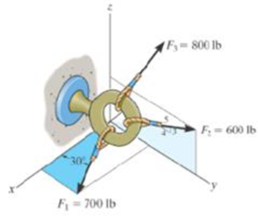
Probs. 2-81/82/83
Expert Solution & Answer
Want to see the full answer?
Check out a sample textbook solution
Students have asked these similar questions
Q5/A: A car with a track of 1.5 m and a wheelbase of 2.9 m has a steering gear
mechanism of the Ackermann type. The distance between the front stub axle pivots
is 1.3 m. The length of each track arm is 150 mm, and the length of the track rod is
1.2 m. Find the angle turned through by the outer wheel if the angle turned through
by the inner wheel is 30°.
(6 Marks)
Q5/B: Write True on the correct sentences and False on the wrong sentences
listed below:-
1- In automobiles, the power is transmitted from the gearbox to the differential
through bevel gears.
2- The minimum radius circle drawn to the cam profile is called the base circle.
3- The Proell governor, compared to the Porter governor, has less lift at the same
speed.
4- The balancing of rotating and reciprocating parts of an engine is necessary when
it runs at a slow speed.
(6.5 Marks)
***Best of Luck ***
جامعة بابل
UNIVERSITY OF BABYLON
Examiner:
Mohanad R. Hameed
Head of Department:
Dr. Dhyai H. Jawad
University of Babylon
Collage of Engineering/
Al-Musayab
Department of Automobiles
Mid Examination/ Stage: 3rd
Subject: Theory of Vehicles
Date: 14 \ 4 \2025
Time: 1.5 Hours
2025-2024
Q1: The arms of a Porter governor are 250 mm long. The upper arms are pivoted on
the axis of revolution, but the lower arms are attached to a sleeve at a distance of 50
mm from the axis of rotation. The weight on the sleeve is 600 N and the weight of
each ball is 80 N. Determine the equilibrium speed when the radius of rotation of the
balls is 150 mm. If the friction is equivalent to a load of 25 N at the sleeve, determine
the range of speed for this position.
Q2: In a loaded Proell governor shown in Figure below each ball weighs 3 kg and
the central sleeve weighs 25 kg. The arms are of 200 mm length and pivoted about
axis displaced from the central axis of rotation by 38.5 mm, y=238 mm, x=303.5
mm, CE 85 mm, MD 142.5 mm. Determine the equilibrium speed.
Fe
mg
E
M
2
Q3: In a spring loaded Hartnell type…
using the theorem of three moments, find all the reactions and supports, I need the calculations only
Chapter 2 Solutions
EP MODIFIED MASTERING ENGINEERING WITH
Ch. 2.3 - In each case, construct the parallelogram law to...Ch. 2.3 - In each case, show how to resolve the force F into...Ch. 2.3 - Determine the magnitude of the resultant force...Ch. 2.3 - Two forces act on the hook. Determine the...Ch. 2.3 - Determine the magnitude of the resultant force and...Ch. 2.3 - Resolve the 30-lb force into components along the...Ch. 2.3 - The force F = 450 lb acts on the frame. Resolve...Ch. 2.3 - If force F is to have a component along the u axis...Ch. 2.3 - If = 60 and F = 450 N, determine the magnitude of...Ch. 2.3 - If the magnitude of the resultant force is to be...
Ch. 2.3 - Determine the magnitude of the resultant force FR...Ch. 2.3 - The vertical force F acts downward at A on the...Ch. 2.3 - Solve with F = 350 lb. Prob. 2-4/5Ch. 2.3 - Determine the magnitude of the resultant force FR...Ch. 2.3 - Resolve the force F1 into components acting along...Ch. 2.3 - Resolve the force F2 into components acting along...Ch. 2.3 - If the resultant force acting on the support is to...Ch. 2.3 - Determine the magnitude of the resultant force and...Ch. 2.3 - The plate is subjected to the two forces at A and...Ch. 2.3 - Determine the angle for connecting member A to...Ch. 2.3 - The force acting on the gear tooth is F = 20lb....Ch. 2.3 - The component of force F acting along line aa is...Ch. 2.3 - Force F acts on the frame such that its component...Ch. 2.3 - Force F acts on the frame such that its component...Ch. 2.3 - Determine the magnitude and direction of the...Ch. 2.3 - Determine the magnitude and direction of the...Ch. 2.3 - Determine the design angle (0 90) for strut AB...Ch. 2.3 - Determine the design angle (0 90) between...Ch. 2.3 - Determine the magnitude and direction of the...Ch. 2.3 - Prob. 22PCh. 2.3 - Prob. 23PCh. 2.3 - Prob. 24PCh. 2.3 - If F1 = 30 lb and F2 = 40 lb, determine the angles...Ch. 2.3 - Determine the magnitude and direction of FA SO...Ch. 2.3 - Determine the magnitude and direction, measured...Ch. 2.3 - Determine the magnitude of force F so that the...Ch. 2.3 - If the resultant force of the two tugboats is 3...Ch. 2.3 - If FB = 3 kN and = 45, determine the magnitude of...Ch. 2.3 - If the resultant force of the two tugboats is...Ch. 2.4 - Resolve each force acting on the post into its x...Ch. 2.4 - Determine the magnitude and direction of the...Ch. 2.4 - Prob. 9FPCh. 2.4 - If the resultant force acting on the bracket is to...Ch. 2.4 - If the magnitude of the resultant force acting on...Ch. 2.4 - Determine the magnitude of the resultant force and...Ch. 2.4 - Determine the magnitude of the resultant force and...Ch. 2.4 - Prob. 33PCh. 2.4 - Prob. 34PCh. 2.4 - Determine the magnitude of the resultant force and...Ch. 2.4 - Resolve each force acting on the gusset plate into...Ch. 2.4 - Determine the magnitude of the resultant force...Ch. 2.4 - Prob. 38PCh. 2.4 - Prob. 39PCh. 2.4 - Determine the magnitude of the resultant force and...Ch. 2.4 - Determine the magnitude of the resultant force and...Ch. 2.4 - Express F1, F2, and F3 as Cartesian vectors.Ch. 2.4 - Prob. 43PCh. 2.4 - Prob. 44PCh. 2.4 - Prob. 45PCh. 2.4 - Determine the magnitude and orientation of FB so...Ch. 2.4 - Determine the magnitude and orientation. measured...Ch. 2.4 - Prob. 48PCh. 2.4 - Prob. 49PCh. 2.4 - Express F1, F2, and F3 as Cartesian vectors.Ch. 2.4 - Prob. 51PCh. 2.4 - Prob. 52PCh. 2.4 - Prob. 53PCh. 2.4 - Prob. 54PCh. 2.4 - Prob. 55PCh. 2.4 - Prob. 56PCh. 2.4 - If the resultant force acting on the bracket is...Ch. 2.4 - Prob. 58PCh. 2.4 - If F = 5 kN and = 30, determine the magnitude of...Ch. 2.6 - Sketch the following forces on the x, y, z...Ch. 2.6 - In each case, establish F as a Cartesian vector,...Ch. 2.6 - Show how to resolve each force into its x, y, z...Ch. 2.6 - Determine the coordinate direction angles of the...Ch. 2.6 - Prob. 14FPCh. 2.6 - Prob. 15FPCh. 2.6 - Prob. 16FPCh. 2.6 - Prob. 17FPCh. 2.6 - Prob. 18FPCh. 2.6 - The force F has a magnitude of 80 lb and acts...Ch. 2.6 - Prob. 61PCh. 2.6 - Prob. 62PCh. 2.6 - Prob. 63PCh. 2.6 - Prob. 64PCh. 2.6 - The screw eye is subjected to the two forces...Ch. 2.6 - Prob. 66PCh. 2.6 - Determine the magnitude and coordinate direction...Ch. 2.6 - Determine the magnitude and coordinate direction...Ch. 2.6 - Determine the magnitude and coordinate direction...Ch. 2.6 - Determine the magnitude and coordinate direction...Ch. 2.6 - Specify the magnitude and coordinate direction...Ch. 2.6 - Prob. 72PCh. 2.6 - Prob. 73PCh. 2.6 - Prob. 74PCh. 2.6 - Prob. 75PCh. 2.6 - Prob. 76PCh. 2.6 - Prob. 77PCh. 2.6 - Prob. 78PCh. 2.6 - Determine the coordinate direction angles of the...Ch. 2.6 - The bracket is subjected to the two forces shown....Ch. 2.6 - Prob. 81PCh. 2.6 - Prob. 82PCh. 2.6 - If the direction of the resultant force acting on...Ch. 2.6 - Prob. 84PCh. 2.6 - The pole is subjected to the force F which has...Ch. 2.8 - In each case, establish a position vector from...Ch. 2.8 - In each case, express F as a Cartesian vector....Ch. 2.8 - Express the position vector rAB in Cartesian...Ch. 2.8 - Prob. 20FPCh. 2.8 - Express the force as a Cartesian vector. Prob....Ch. 2.8 - Prob. 22FPCh. 2.8 - Prob. 23FPCh. 2.8 - Prob. 24FPCh. 2.8 - Determine the length of the connecting rod AB by...Ch. 2.8 - Express force F as a Cartesian vector; then...Ch. 2.8 - Prob. 88PCh. 2.8 - Prob. 89PCh. 2.8 - Prob. 90PCh. 2.8 - Prob. 91PCh. 2.8 - Prob. 92PCh. 2.8 - If FB = 560 N and FC = 700 N, determine the...Ch. 2.8 - If FB = 700 N, and FC = 560 N, determine the...Ch. 2.8 - The plate is suspended using the three cables...Ch. 2.8 - The three supporting cables exert the forces shown...Ch. 2.8 - Determine the magnitude and coordinate direction...Ch. 2.8 - Prob. 98PCh. 2.8 - Prob. 99PCh. 2.8 - Prob. 100PCh. 2.8 - The two mooring cables exert forces on the stern...Ch. 2.8 - Prob. 102PCh. 2.8 - Determine the magnitude and coordinate direction...Ch. 2.8 - If the force in each cable tied to the bin is 70...Ch. 2.8 - If the resultant of the four forces is FR = {360k}...Ch. 2.9 - P2.8. in each case set up the dot product to find...Ch. 2.9 - Prob. 9PPCh. 2.9 - Prob. 25FPCh. 2.9 - Determine the angle between the force and the...Ch. 2.9 - Prob. 27FPCh. 2.9 - Prob. 28FPCh. 2.9 - Find the magnitude of the projected component of...Ch. 2.9 - Prob. 30FPCh. 2.9 - Determine the magnitudes of the components of the...Ch. 2.9 - Prob. 106PCh. 2.9 - Prob. 107PCh. 2.9 - Prob. 108PCh. 2.9 - Prob. 109PCh. 2.9 - Prob. 110PCh. 2.9 - Prob. 111PCh. 2.9 - Prob. 112PCh. 2.9 - Determine the magnitudes of the components of F =...Ch. 2.9 - Prob. 114PCh. 2.9 - Prob. 115PCh. 2.9 - Prob. 116PCh. 2.9 - Determine the magnitudes of the projected...Ch. 2.9 - Determine the angle between cables AB and AC....Ch. 2.9 - Prob. 119PCh. 2.9 - Prob. 120PCh. 2.9 - Determine the angle between the two cables...Ch. 2.9 - Determine the angle between the cables AB and AC....Ch. 2.9 - Determine the magnitude of the projected component...Ch. 2.9 - Determine the magnitude of the projected component...Ch. 2.9 - Determine the magnitude of the projection of force...Ch. 2.9 - Prob. 126PCh. 2.9 - Prob. 127PCh. 2.9 - Prob. 128PCh. 2.9 - Determine the magnitude of the projected component...Ch. 2.9 - Prob. 130PCh. 2.9 - Prob. 131PCh. 2.9 - Determine the magnitude of the projected component...Ch. 2.9 - Prob. 133PCh. 2.9 - Prob. 134PCh. 2.9 - Prob. 135PCh. 2.9 - Prob. 136PCh. 2.9 - Prob. 137PCh. 2.9 - Prob. 138PCh. 2.9 - Prob. 139PCh. 2.9 - Determine the magnitude of the resultant force FR...Ch. 2.9 - Resolve F into components along the u and v axes...Ch. 2.9 - Prob. 3RPCh. 2.9 - The cable at the end of the crane boom exerts a...Ch. 2.9 - Prob. 5RPCh. 2.9 - Prob. 6RPCh. 2.9 - Prob. 7RPCh. 2.9 - Prob. 8RP
Knowledge Booster


Learn more about
Need a deep-dive on the concept behind this application? Look no further. Learn more about this topic, mechanical-engineering and related others by exploring similar questions and additional content below.Similar questions
- Q.5: (10 Marks) Select the correct answer (choose 10 only) 1. The forward whirling speed is ......... the static structure tilting speed. (a) Less than (b) Higher than (c) equal to 2. The divergence between the forward and backward whirling speeds increases as: (a) The rotating speed increase (b) the polar moment of inertia increases (c) Both (a) and (b) (d) do not change 3. Increasing the system natural frequency can be done by: (a) add masses (b) adding braces and supports (c) increase damping 4. The amplitude of vibration due to external force can be reduced by: (a) Increasing damping (b) Decreasing damping (c) Increasing mass 5. Tuned absorbers are used to: (a) Shift the natural frequency (b) increase damping (c) Increase stiffness 6. Accelerometers sensors contains: г (a) Piezoelectric materials (b) Magnet and coil (c) coil only 7. Increasing the stiffness of the system causes: (a) Less transmitted force (b) more transmitted force (c) Transmitted force does not change 8. The…arrow_forwardQ.1: (15 Marks) Find the first three natural frequencies and mode shapes of the axial and torsional vibration for a steel shaft free at both ends, having a length of 3 m. Find the subsequent axil motion if the shaft is subjected to the following initial conditions, given that E = 210 GPa, G=80 GPa, p = 7800 kg/m³: f(x)=0 v(x) = {1 2.8arrow_forwardQ.4: (15 Marks) A uniform rotor of mass 500 kg and diametral moment of inertia of 20 kg.m², is supported by identical short bearings of stiffness 1 MN/m in the horizontal and vertical directions. If the distance between the bearings is 0.6 m: (a) What is the corresponding polar moment of inertia if the backward whirling speed is 80% of the static structure tilting natural frequency? (b) Determine the forward whirling speed. 45.27arrow_forwardUniversity of Babylon Collage of Engineering/ Al-Musayab Department of Automobiles Mid Examination/ Stage: 3rd Subject: Theory of Vehicles Date: 14 \ 4 \2025 Time: 1.5 Hours 2025-2024 Q1: The arms of a Porter governor are 250 mm long. The upper arms are pivoted on the axis of revolution, but the lower arms are attached to a sleeve at a distance of 50 mm from the axis of rotation. The weight on the sleeve is 600 N and the weight of each ball is 80 N. Determine the equilibrium speed when the radius of rotation of the balls is 150 mm. If the friction is equivalent to a load of 25 N at the sleeve, determine the range of speed for this position. Q2: In a loaded Proell governor shown in Figure below each ball weighs 3 kg and the central sleeve weighs 25 kg. The arms are of 200 mm length and pivoted about axis displaced from the central axis of rotation by 38.5 mm, y=238 mm, x=303.5 mm, CE 85 mm, MD 142.5 mm. Determine the equilibrium speed. Fe mg E M 2 Q3: In a spring loaded Hartnell type…arrow_forwardQ.2: (15 Marks) = 1400 For the following system, determine the first natural frequency using Dunkerley's equation, Given that the disk has moment of inertia J = 2 kg.m², the shaft has G = 20 GPa, p kg/m³, polar moment of cross-sectional area of the shaft Ip = 8×10⁸ m². 500 mm 220 mm k=200 N/m FOF m=1 kg 14.14 56.56. W слarrow_forwardQ.2: (15 Marks) = 1400 For the following system, determine the first natural frequency using Dunkerley's equation, Given that the disk has moment of inertia J = 2 kg.m², the shaft has G = 20 GPa, p kg/m³, polar moment of cross-sectional area of the shaft Ip = 8×10⁸ m². 500 mm 220 mm k=200 N/m FOF m=1 kg 14.14 56.56. W слarrow_forwardQ1: In Figure below, pinion A having 15 teeth is fixed to motor shaft. Za-20, Z-15, where B and C are a compound gear wheel. Wheel E is keyed to the machine shaft. Arm F rotates about the same shaft on which A is fixed and carries the compound wheel B, C. If the motor runs at 1200 rpm counter-clockwise, find (a) the speed of the machine shaft and (b) ratio of the reduction gear. C B D Q1: A compound epicyclic gear is shown diagrammatically in Figure below. The gears A, D and E are free to rotate on the axis P. The compound gear B and C rotate together on the axis Q at the end of arm F. All the gears have equal pitch. The number of external teeth on the gears A, B and C are 18, 45 and 21 respectively. The gears D and E are annular gears. The gear A rotates at 100 r.p.m. in the anticlockwise direction and the gear D rotates at 450 r.p.m. clockwise. Find the speed and direction of the arm and the gear E. D E A P F LL B Carrow_forwardCalculate the force in cable AB and the angle θ for the support system shown. Round your final answers to two decimal places.arrow_forward1.53 In the steel structure shown, a 6-mm-diameter pin is used at C and 10-mm-diameter pins are used at B and D. The ultimate shearing stress is 150 MPa at all connections, and the ultimate normal stress is 400 MPa in link BD. Knowing that a factor of safety of 3.0 is desired, determine the largest load P that can be applied at A. Note that link BD is not reinforced around the pin holes. Front view D D 6 mm 18 mm B A B Side view 160 mm 120 mm A B Top viewarrow_forwardCORRECT AND DETAILED HANDWRITTEN SOLUTION WITH FBD ONLY. I WILL UPVOTE THANK YOU. CORRECT ANSWER IS ALREADY PROVIDED. 16: Determine (a) the maximum bending stress, (b)the maximum shearing stress, (c) compressive bending stress atthe roller support, and (d) the shearing stress 1 in below the topsurface of the beam at the location 1 ft to the right of the rollersupport in the simply supported beam shown in Fig. 8-70.ANS: (a) 21,945.313 lb/in2; (b) 1656.25 lb/in2; (c) 10,000 lb/in2; (d) 190.972 lb/in2arrow_forwardCORRECT AND DETAILED HANDWRITTEN SOLUTION WITH FBD ONLY. I WILL UPVOTE THANK YOU. CORRECT ANSWER IS ALREADY PROVIDED. 20: A 2022 Porsche 911 (992) GT3 is crossing a 20 ft bridge. The specification of the car is shown below.Determine the maximum shear (in lb) and moment (in lb-ft) on the bridge. ANS: Vmax = 2,680.850 lb ; Mmax = 11,233.13 lb-ftarrow_forwardCORRECT AND DETAILED HANDWRITTEN SOLUTION WITH FBD ONLY. I WILL UPVOTE THANK YOU. CORRECT ANSWER IS ALREADY PROVIDED. Answers: P1 = 208.625 KN/M P2 = 281.310 KN/M P = 15.491 KN/M FB = 463.402 MPA FV = 55.034 MPAarrow_forwardarrow_back_iosSEE MORE QUESTIONSarrow_forward_ios
Recommended textbooks for you
 Elements Of ElectromagneticsMechanical EngineeringISBN:9780190698614Author:Sadiku, Matthew N. O.Publisher:Oxford University Press
 Mechanics of Materials (10th Edition)Mechanical EngineeringISBN:9780134319650Author:Russell C. HibbelerPublisher:PEARSON
 Thermodynamics: An Engineering ApproachMechanical EngineeringISBN:9781259822674Author:Yunus A. Cengel Dr., Michael A. BolesPublisher:McGraw-Hill Education
 Control Systems EngineeringMechanical EngineeringISBN:9781118170519Author:Norman S. NisePublisher:WILEY
 Mechanics of Materials (MindTap Course List)Mechanical EngineeringISBN:9781337093347Author:Barry J. Goodno, James M. GerePublisher:Cengage Learning
 Engineering Mechanics: StaticsMechanical EngineeringISBN:9781118807330Author:James L. Meriam, L. G. Kraige, J. N. BoltonPublisher:WILEY
Elements Of Electromagnetics
Mechanical Engineering
ISBN:9780190698614
Author:Sadiku, Matthew N. O.
Publisher:Oxford University Press
Mechanics of Materials (10th Edition)
Mechanical Engineering
ISBN:9780134319650
Author:Russell C. Hibbeler
Publisher:PEARSON
Thermodynamics: An Engineering Approach
Mechanical Engineering
ISBN:9781259822674
Author:Yunus A. Cengel Dr., Michael A. Boles
Publisher:McGraw-Hill Education
Control Systems Engineering
Mechanical Engineering
ISBN:9781118170519
Author:Norman S. Nise
Publisher:WILEY
Mechanics of Materials (MindTap Course List)
Mechanical Engineering
ISBN:9781337093347
Author:Barry J. Goodno, James M. Gere
Publisher:Cengage Learning
Engineering Mechanics: Statics
Mechanical Engineering
ISBN:9781118807330
Author:James L. Meriam, L. G. Kraige, J. N. Bolton
Publisher:WILEY
How to balance a see saw using moments example problem; Author: Engineer4Free;https://www.youtube.com/watch?v=d7tX37j-iHU;License: Standard Youtube License