(a)
The current in the
(a)
Answer to Problem 54AP
The current in
Explanation of Solution
Write the expression based on the junction rule.
Here,
Write the expression to obtain the loop rule.
Here,
Write the expression for the potential difference based on Ohm’s law.
Here,
The flow of current in the circuit is as shown in the figure below.
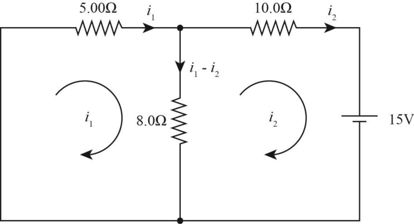
Figure-(1)
Here,
Write the equation of Kirchhoff’s voltage rule in the left loop.
Write the equation of Kirchhoff’s voltage rule in the right loop.
Conclusion:
Solve equation (I) and (II) to calculate
Therefore, the current in
(b)
The power delivered to the
(b)
Answer to Problem 54AP
The power delivered to the
Explanation of Solution
Write the expression to obtain the power across the
Here,
Conclusion:
Substitute
Therefore, the power delivered to the
(c)
The circuit in which Kirchhoff’s rule is required in find the value of current.
(c)
Answer to Problem 54AP
The Kirchhoff’s rule is required to find the value of current in case of circuit (c).
Explanation of Solution
In case of circuit (c), the current is flowing across each resistor and voltage drops at each resistor. As both the batteries of same emf are not in the same loop, thus, some amount of current will flow in the circuit. Hence, Kirchhoff’s rule is applicable in this case.
Conclusion:
In the case of the other two circuits, both the batteries of same emf are in the same loop. Thus they cancel out each other and no current flow in the circuit (b) and circuit (d).
Therefore, The Kirchhoff’s rule is required in find the value of current in case of circuit (c).
(d)
The circuit in which the smallest amount of power is delivered to the
(d)
Answer to Problem 54AP
The smallest power is delivered across the
Explanation of Solution
Conclusion:
The current flow diagram for circuit (b) is as shown in the figure below.
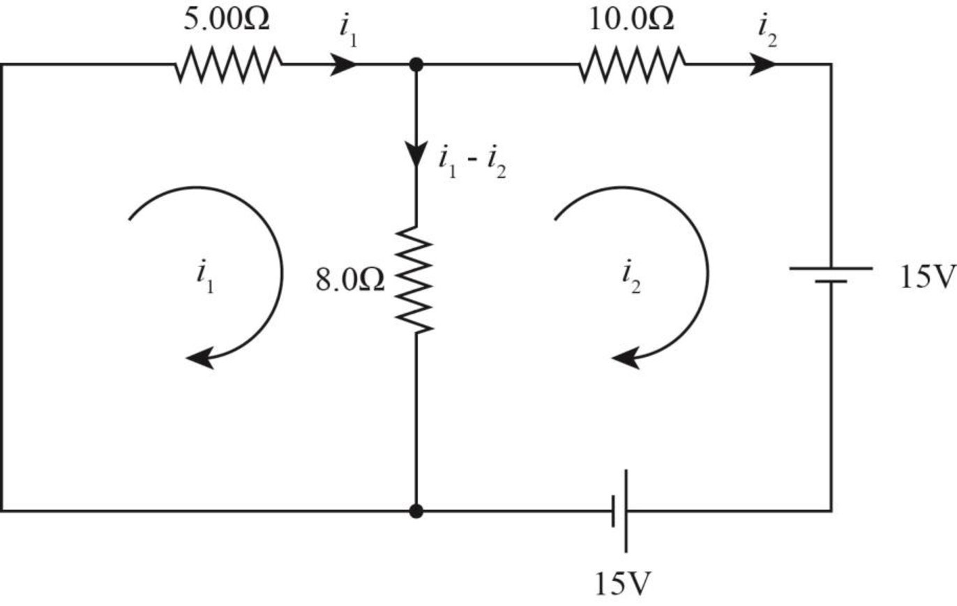
Figure-(2)
Write the equation of Kirchhoff’s voltage rule in right loop.
Write the expression based on junction rule.
Solve equation (III) and (IV) to calculate
Thus, the current across the circuit (b) is zero.
Therefore, the power delivered to across
The current flow diagram for circuit (c) is as shown in the figure below.
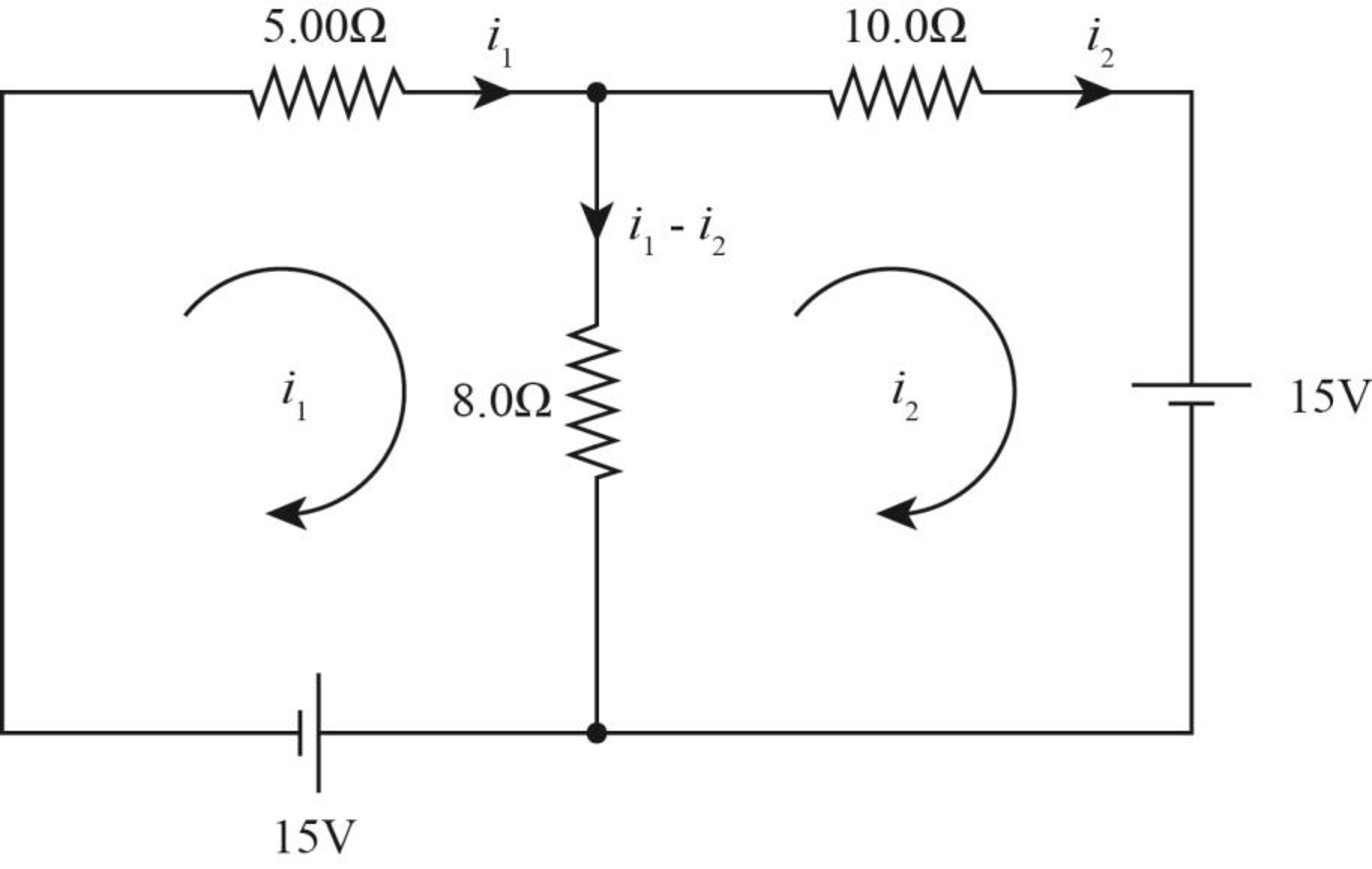
Figure-(3)
Write the equation of Kirchhoff’s voltage rule in the left loop.
Write the equation of Kirchhoff’s voltage rule in the left loop.
Solve equation (V) and (VI) to calculate
Write the expression to obtain the power across the
Here,
Substitute
Therefore, the power delivered to the
The current flow diagram for circuit (d) is as shown in the figure below.
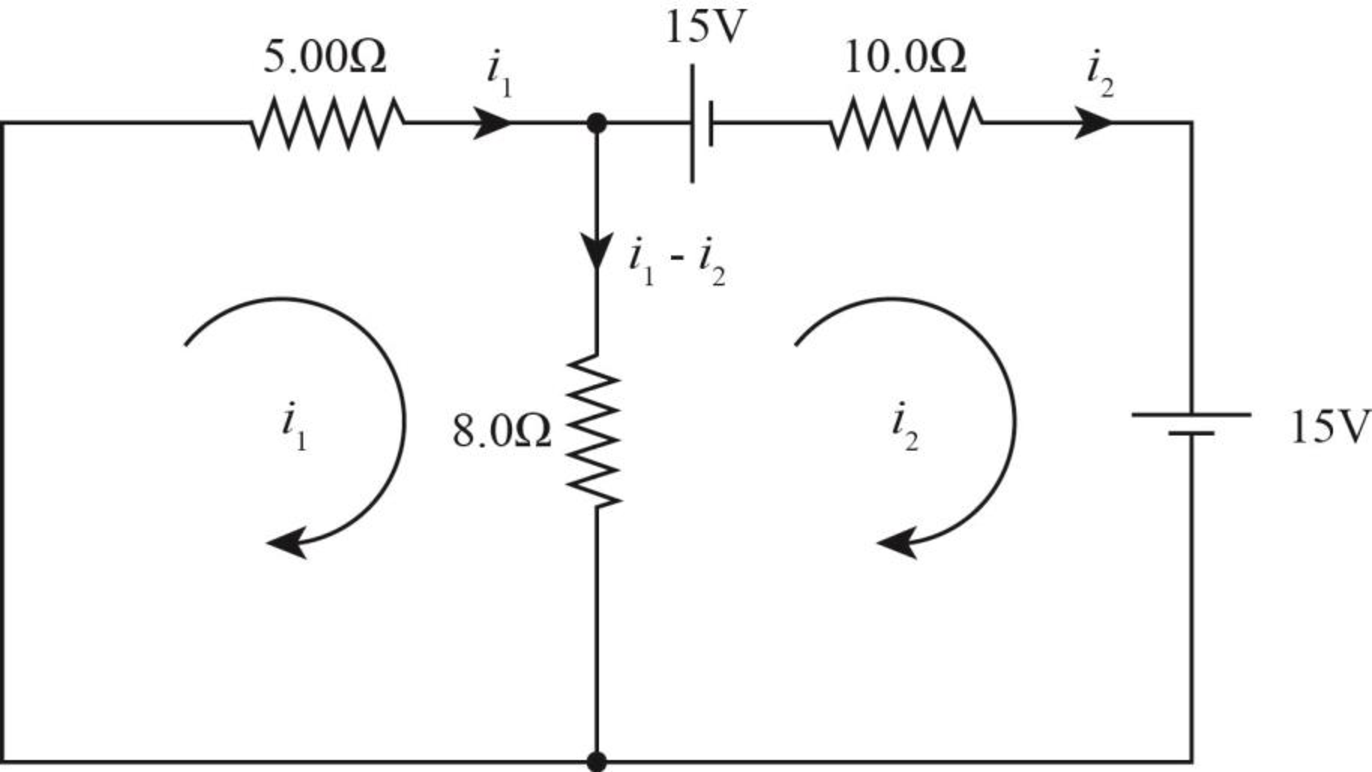
Figure-(4)
Write the equation of Kirchhoff’s voltage rule in left loop.
Write the equation of Kirchhoff’s voltage rule in left loop.
Solve equation (VII) and (VIII) to calculate
Thus, the current across the circuit (d) is zero.
Therefore, the power delivered to across
Therefore the smallest power is delivered across
Want to see more full solutions like this?
Chapter 28 Solutions
Physics for Scientists and Engineers With Modern Physics
- John is pushing his daughter Rachel in a wheelbarrow when it is stopped by a brick 8.00 cm high (see the figure below). The handles make an angle of 0 = 17.5° with the ground. Due to the weight of Rachel and the wheelbarrow, a downward force of 403 N is exerted at the center of the wheel, which has a radius of 16.0 cm. Assume the brick remains fixed and does not slide along the ground. Also assume the force applied by John is directed exactly toward the center of the wheel. (Choose the positive x-axis to be pointing to the right.) (a) What force (in N) must John apply along the handles to just start the wheel over the brick? (No Response) N (b) What is the force (magnitude in kN and direction in degrees clockwise from the -x-axis) that the brick exerts on the wheel just as the wheel begins to lift over the brick? magnitude (No Response) KN direction (No Response) ° clockwise from the -x-axisarrow_forwardAn automobile tire is shown in the figure below. The tire is made of rubber with a uniform density of 1.10 × 10³ kg/m³. The tire can be modeled as consisting of two flat sidewalls and a tread region. Each of the sidewalls has an inner radius of 16.5 cm and an outer radius of 30.5 cm as shown, and a uniform thickness of 0.600 cm. The tread region can be approximated as having a uniform thickness of 2.50 cm (that is, its inner radius is 30.5 cm and outer radius is 33.0 cm as shown) and a width of 19.2 cm. What is the moment of inertia (in kg. m²) of the tire about an axis perpendicular to the page through its center? 2.18 x Sidewall 33.0 cm 30.5 cm 16.5 cm Treadarrow_forwardA person on horseback is on a drawbridge which is at an angle = 20.0° above the horizontal, as shown in the figure. The center of mass of the person-horse system is d = 1.35 m from the end of the bridge. The bridge is l = 7.00 m long and has a mass of 2,300 kg. A cable is attached to the bridge 5.00 m from the frictionless hinge and to a point on the wall h = 12.0 m above the bridge. The mass of person plus horse is 1,100 kg. Assume the bridge is uniform. Suddenly (and most unfortunately for the horse and rider), the ledge where the bridge usually rests breaks off, and at the same moment the cable snaps and the bridge swings down until it hits the wall. ÚI MAJI A TLA MAJA AUTA (a) Find the angular acceleration (magnitude, in rad/s²) of the bridge once it starts to move. 2.22 Use the rotational analogue of Newton's second law. The drawbridge can be modeled as a rod, with rotation axis about one end. rad/s² (b) How long (in s) does the horse and rider stay in contact with the bridge…arrow_forward
- Two long, parallel wires carry currents of I₁ = 2.70 A and I2 = 4.85 A in the directions indicated in the figure below, where d = 22.0 cm. (Take the positive x direction to be to the right.) 12 (a) Find the magnitude and direction of the magnetic field at a point midway between the wires. magnitude direction 3.91 270 μπ ⚫ counterclockwise from the +x axis (b) Find the magnitude and direction of the magnetic field at point P, located d = 22.0 cm above the wire carrying the 4.85-A current. magnitude direction Your response differs significantly from the correct answer. Rework your solution from the beginning and check each step carefully. μT The response you submitted has the wrong sign.° counterclockwise from the +x axisarrow_forwardO Macmillan Learning The mass of a particular eagle is twice that of a hunted pigeon. Suppose the pigeon is flying north at Vi2 = 16.1 m/s when the eagle swoops down, grabs the pigeon, and flies off. At the instant right before the attack, the eagle is flying toward the pigeon at an angle 0 = 64.3° below the horizontal and a speed of Vi,1 = 37.9 m/s. What is the speed of of the eagle immediately after it catches its prey? What is the magnitude & of the angle, measured from horizontal, at which the eagle is flying immediately after the strike? Uf = II x10 TOOLS Vi.1 Vi,2 m/sarrow_forwardWhat is the equivalent resistance if you connect a 1.7 Ohm, a 9.3 Ohm, and a 22 Ohm resistor in series? (Give your answer as the number of Ohms.)arrow_forward
- Three wires meet at a junction. One wire carries a current of 5.2 Amps into the junction, and a second wire carries a current of 3.7 Amps out of the junction. What is the current in the third wire? Give your answer as the number of Amps, and give a positive number if the current in that wire flows out of the junction, or a negative number if the current in that wire flows into the junction.arrow_forwardWhat is the equivalent resistance if you connect a 4.5 Ohm, a 6.8 Ohm, and a 15 Ohm resistor in parallel? (Give your answer as the number of Ohms.)arrow_forwardSuppose a heart defibrillator passes 10.5 Amps of current through a patient's torso for 5.0 x 10⁻³ seconds in order to restore a regular heartbeat. The voltage across the defibrillator is 9800 volts for the entire time that current is flowing. If 7.25 kg of body tissue is involved, with a specific heat of 3500 J/(kg°C), then what is the resulting temperature increase of the person's torso? (Give your answer as the number of degrees C.)arrow_forward
- The figure below is a cross-sectional view of a coaxial cable. The center conductor is surrounded by a rubber layer, an outer conductor, and another rubber layer. In a particular application, the current in the inner conductor is I₁ = 1.04 A out of the page and the current in the outer conductor is I2 = 2.90 A into the page. Assuming the distance d = 1.00 mm, answer the following. 4 12 (a) Determine the magnitude and direction of the magnetic field at point a. magnitude 208 direction upward (b) Determine the magnitude and direction of the magnetic field at point b. magnitude direction 238 You can approach this problem by finding the field produced by current I₁ and the field produced by I2 and then adding them vectorially. μT downwardarrow_forwardShoto, from My Hero Academia, has a power (or a “quirk”) that allows him to make large amounts of ice from nothing. Let us say that due to a fire a 361 kg steel beam is heated to 943.˚C and Shoto creates 390. kg of ice at 0.00˚C around it to cool it down. What is the final temperature of the system after the ice melts and it reaches thermal equilibrium? The specific heat of steel is 502 J/kg˚C. The specific heat of water is 4186 J/kg˚C. The latent heat of fusion for ice is 3.33⋅10^5 J/kg.arrow_forwardA 25.0 cm long organ pipe is filled with air and is open at one end and closed at the other. The speed of sound in air at 0°C is 331 m/s. What is the frequency of the fourth mode of vibration? Multiple Choice О 1,550 Hz О 1,750 Hz О 2,320 Hz О 2,720 Hz О 3,170 Hzarrow_forward
 Physics for Scientists and Engineers: Foundations...PhysicsISBN:9781133939146Author:Katz, Debora M.Publisher:Cengage Learning
 Principles of Physics: A Calculus-Based TextPhysicsISBN:9781133104261Author:Raymond A. Serway, John W. JewettPublisher:Cengage Learning
 Physics for Scientists and Engineers, Technology ...PhysicsISBN:9781305116399Author:Raymond A. Serway, John W. JewettPublisher:Cengage Learning
 College PhysicsPhysicsISBN:9781305952300Author:Raymond A. Serway, Chris VuillePublisher:Cengage Learning
 College PhysicsPhysicsISBN:9781285737027Author:Raymond A. Serway, Chris VuillePublisher:Cengage Learning
 Physics for Scientists and Engineers with Modern ...PhysicsISBN:9781337553292Author:Raymond A. Serway, John W. JewettPublisher:Cengage Learning


