Concept explainers
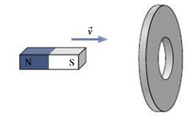
In Fig. 27.35, a bar magnet moves toward a

FIGURE 27.35 For Thought and Discussion 1
The direction of the induced current in the ring.
Answer to Problem 1FTD
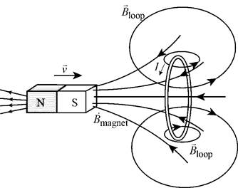
The direction of the induced current in the ring is shown in Figure 1.
Explanation of Solution
According to the Lenz’s law, the induced current in the ring will produce a magnetic field, which will oppose the change in flux in the ring. Since the south pole of the bar magnet is pushed towards the conducting ring, the ring will produce a magnetic field, which opposes the change in flux due to the magnet. Thus by applying the right-hand rule gives the direction of current flow through the ring as shown in Figure 1.

Figure 1
Conclusion:
Therefore, the direction of the induced current in the ring is shown in Figure 1.
Want to see more full solutions like this?
Chapter 27 Solutions
Essential University Physics (3rd Edition)
Additional Science Textbook Solutions
Microbiology with Diseases by Body System (5th Edition)
Campbell Essential Biology with Physiology (5th Edition)
Anatomy & Physiology (6th Edition)
Microbiology: An Introduction
Campbell Essential Biology (7th Edition)
Cosmic Perspective Fundamentals
- A car driving at 27m/s veers to the left to avoid a deer in the road. The maneuver takes 2.0s and the direction of travel is altered by 20 degrees. What is the average acceleration during the constant speed maneuver? Do this in accordance with the example in the chapter.arrow_forwardNo No No Chatgpt pls will upvotearrow_forward2 C01: Physical Quantities, Units and Measurementscobris alinu zotinUD TRO Bendemeer Secondary School Secondary Three Express Physics Chpt 1: Physical Quantities, Unit and Measurements Assignment Name: Chen ShiMan loov neowled soria 25 ( 03 ) Class: 3 Respect 6 Date: 2025.01.22 1 Which group consists only of scalar quantities? ABCD A acceleration, moment and energy store distance, temperature and time length, velocity and current mass, force and speed B D. B Which diagram represents the resultant vector of P and Q? lehtele 시 bas siqpeq olarist of beau eldeo qirie-of-qi P A C -B qadmis rle mengaib priwollot erT S Quilons of qira ono mont aboog eed indicator yh from West eril to Inioqbim srij enisinoo MA (6) 08 bas 8A aldao ni nolent or animaleb.gniweb slepe eld 260 km/h D 1 D. e 51arrow_forward
- The figure gives the acceleration a versus time t for a particle moving along an x axis. The a-axis scale is set by as = 12.0 m/s². At t = -2.0 s, the particle's velocity is 11.0 m/s. What is its velocity at t = 6.0 s? a (m/s²) as -2 0 2 t(s) 4arrow_forwardTwo solid cylindrical rods AB and BC are welded together at B and loaded as shown. Knowing that the average normal stress must not exceed 150 MPa in either rod, determine the smallest allowable values of the diameters d₁ and d2. Take P= 85 kN. P 125 kN B 125 kN C 0.9 m 1.2 m The smallest allowable value of the diameter d₁ is The smallest allowable value of the diameter d₂ is mm. mm.arrow_forwardWestros, from Game of Thrones, has an area of approximately 6.73⋅106 miles26.73⋅106miles2. Convert the area of Westros to km2 where 1.00 mile = 1.609 km.arrow_forward
- a) What is the lenght of x? b) Findθ c) Find ϕarrow_forwardA surveyor measures the distance across a straight river by the following method: Starting directly across from a tree on the opposite bank, he walks x = 97.7 m along the riverbank to establish a baseline. Then he sights across to the tree. The angle from his baseline to the tree is θ = 33.0 °. How wide is the river?arrow_forwardA small turtle moves at a speed of 697. furlong/fortnight. Find the speed of the turtle in centimeters per second. Note that 1.00 furlong = 220. yards, 1.00 yard = 3.00 feet, 1.00 foot = 12.0 inches, 1.00 inch = 2.54 cm, and 1.00 fortnight = 14.0 days.arrow_forward
- The landmass of Sokovia lifted in the air in Avengers: Age of Ultron had a volume of about 1.98 km3. What volume is that in m3?arrow_forwardA fathom is a unit of length, usually reserved for measuring the depth of water. A fathom is exactly 6.00 ft in length. Take the distance from Earth to the Moon to be 252,000 miles, and use the given approximation to find the distance in fathoms. 1 mile = 5280 ft. (Answer in sig fig.)arrow_forwardNo chatgpt pls will upvotearrow_forward

 Physics for Scientists and EngineersPhysicsISBN:9781337553278Author:Raymond A. Serway, John W. JewettPublisher:Cengage Learning
 Physics for Scientists and Engineers with Modern ...PhysicsISBN:9781337553292Author:Raymond A. Serway, John W. JewettPublisher:Cengage Learning
 Physics for Scientists and Engineers: Foundations...PhysicsISBN:9781133939146Author:Katz, Debora M.Publisher:Cengage Learning
 Glencoe Physics: Principles and Problems, Student...PhysicsISBN:9780078807213Author:Paul W. ZitzewitzPublisher:Glencoe/McGraw-Hill
 College PhysicsPhysicsISBN:9781285737027Author:Raymond A. Serway, Chris VuillePublisher:Cengage Learning


