
Physics for Scientists and Engineers with Modern Physics
4th Edition
ISBN: 9780131495081
Author: Douglas C. Giancoli
Publisher: Addison-Wesley
expand_more
expand_more
format_list_bulleted
Videos
Textbook Question
Chapter 26, Problem 9Q
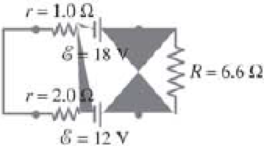
When applying Kirchhoff’s loop rule (such as in Fig. 26–33), does the sign (or direction) of a battery’s emf depend on the direction of current through the battery? What about the terminal voltage?
FIGURE 26–33 Question 9.
Expert Solution & Answer
Want to see the full answer?
Check out a sample textbook solution
Students have asked these similar questions
When applying Kirchhoff's loop rule (such as in Fig. 19–36),
does the sign (or direction) of a battery's emf depend on
the direction of current through the battery? What about
the terminal voltage?
r= 1.0 2
E = 18 V
R=6.6 N
r= 2.0 Q
FIGURE 19-36
Question 10.
E = 12 V
35 (a) For the circuit shown in Fig. 20-27, let & =
10 V, R = 5.0 N, and C = 0.1 F. What is the current
at b just after the switch is closed?
(b) How much charge will have passed b by the time
%3D
%3D
%3D
the current goes to zero?
(c) Find the current at the instant the capacitor has a
charge of 0.20 C.
9.
Soitch S
4) Based on the circuit to the right
answer the folowing questbons,
SHOW ALL WORK
ourrent flows h
STEADY STATE
(a) The equivalent capacitance and
resistance is
20uF
c2
(1)
(11)
()
(iv)
26ul, 19kn
5.0uF, 6.0kn
2 5.F. 3 Oko
12V
R1
15uF, 14k)
30
Chapter 26 Solutions
Physics for Scientists and Engineers with Modern Physics
Ch. 26.1 - Repeat Example 261 assuming now that the...Ch. 26.2 - You have a 10- and a 15- resistor. What is the...Ch. 26.3 - Write the equation for the lower loop abcdefga of...Ch. 26.4 - If the jumper cables of Example 2610 were...Ch. 26.5 - In 10 times constants, the charge on the capacitor...Ch. 26 - Explain why birds can sit on power lines safely,...Ch. 26 - Discuss the advantages and disadvantages of...Ch. 26 - If all you have is a 120-V line, would it be...Ch. 26 - Two lightbulbs of resistance R1 and R2 (R2 R1)...Ch. 26 - Household outlets are often double outlets. Are...
Ch. 26 - With two identical lightbulbs and two identical...Ch. 26 - If two identical resistors are connected in series...Ch. 26 - You have a single 60-W bulb on in your room. How...Ch. 26 - When applying Kirchhoffs loop rule (such as in...Ch. 26 - Compare and discuss the formulas for resistors and...Ch. 26 - For what use are batteries connected in series?...Ch. 26 - Can the terminal voltage of a battery ever exceed...Ch. 26 - Explain in detail how you could measure the...Ch. 26 - In an RC circuit, current flows from the battery...Ch. 26 - Given the circuit shown in Fig. 2634, use the...Ch. 26 - Figure 2635 is a diagram of a capacitor (or...Ch. 26 - Design a circuit in which two different switches...Ch. 26 - What is the main difference between an analog...Ch. 26 - What would happen if you mistakenly used an...Ch. 26 - Explain why an ideal ammeter would have zero...Ch. 26 - A voltmeter connected across a resistor always...Ch. 26 - A small battery-operated flashlight requires a...Ch. 26 - Different lamps might have batteries connected in...Ch. 26 - Prob. 1PCh. 26 - (I) Four 1.50-V cells are connected in series to a...Ch. 26 - (II) A 1.5-V dry cell can be tested by connecting...Ch. 26 - (II) What is the internal resistance of a 12.0-V...Ch. 26 - (I) A 650- and a 2200- resistor are connected in...Ch. 26 - (I) Three 45- lightbulbs and three 65- lightbulbs...Ch. 26 - (I) Suppose that you have a 680-, a 720-, and a...Ch. 26 - (I) How many 10- resistors must be connected in...Ch. 26 - (II) Suppose that you have a 9.0-V battery and you...Ch. 26 - Three 1.70-k resistors can be connected together...Ch. 26 - (II) A battery with an emf of 12.0 V shows a...Ch. 26 - (II) Eight identical bulbs are connected in series...Ch. 26 - (II) Eight bulbs are connected in parallel to a...Ch. 26 - (II) The performance of the starter circuit in an...Ch. 26 - (II) A close inspection of an electric circuit...Ch. 26 - (II) Determine (a) the equivalent resistance of...Ch. 26 - (II) A 75-W, 110-V bulb is connected in parallel...Ch. 26 - (II) (a) Determine the equivalent resistance of...Ch. 26 - (II) Whal is the net resistance of the circuit...Ch. 26 - (II) Calculate the current through each resistor...Ch. 26 - (II) The two terminals of a voltage source with...Ch. 26 - (II) Two resistors when connected in series to a...Ch. 26 - (III) Three equal resistors (R) are connected to a...Ch. 26 - (III) A 2.8-k and a 3.7-k resistor are connected...Ch. 26 - (III) Consider the network of resistors shown in...Ch. 26 - (III) You are designing a wire resistance heater...Ch. 26 - (I) Calculate the current in the circuit of Fig....Ch. 26 - (II) Determine the terminal voltage of each...Ch. 26 - (II) For the circuit shown in Fig. 2647, find the...Ch. 26 - (II) (a) A network of five equal resistors R is...Ch. 26 - (II) (a) What is the potential difference between...Ch. 26 - (II) Calculate the currents in each resistor of...Ch. 26 - (II) Determine the magnitudes and directions of...Ch. 26 - (II) Determine the magnitudes and directions of...Ch. 26 - (II) A voltage V is applied to n identical...Ch. 26 - (III) (a) Determine the currents I1, I2, and I3 in...Ch. 26 - (III) What would the current I1 be in Fig. 2653 if...Ch. 26 - (III) Determine the current through each of the...Ch. 26 - (III) If the 25- resistor in Fig. 2654 is shorted...Ch. 26 - (III) Twelve resistors, each of resistance R, are...Ch. 26 - (III) Determine the net resistance in Fig. 2656...Ch. 26 - (II) Suppose two batteries, with unequal emfs of...Ch. 26 - (I) Estimate the range of resistance needed to...Ch. 26 - (II) In Fig. 2658 (same as Fig. 2617a), the total...Ch. 26 - (II) Two 3.8-F capacitors, two 2.2-k resistors,...Ch. 26 - (II) How long does it take for the energy stored...Ch. 26 - (II) A parallel-plate capacitor is filled with a...Ch. 26 - (II) The RC circuit of Fig. 2659 (same as Fig....Ch. 26 - (II) Consider the circuit shown in Fig. 2660,...Ch. 26 - (III) Determine the time constant for charging the...Ch. 26 - (III) Two resistors and two uncharged capacitors...Ch. 26 - (III) Suppose the switch S in Fig. 2662 is closed....Ch. 26 - (I) An ammeter has a sensitivity of 35,00 /V. What...Ch. 26 - (I) What is the resistance of a voltmeter on the...Ch. 26 - (II) A galvanometer has a sensitivity of 45 k/V...Ch. 26 - (II) A galvanometer has an internal resistance of...Ch. 26 - (II) A particular digital meter is based on an...Ch. 26 - (II) A milliammeter reads 25 mA full scale. It...Ch. 26 - (II) A 45-V battery of negligible internal...Ch. 26 - (II) An ammeter whose internal resistance is 53 ...Ch. 26 - (II) A battery with E=12.0V and internal...Ch. 26 - (II) A 12.0-V battery (assume the internal...Ch. 26 - (III) Two 9.4-k resistors are placed in series and...Ch. 26 - (III) When the resistor R in Fig. 2664 is 35 , the...Ch. 26 - Suppose that you wish to apply a 0.25-V potential...Ch. 26 - A three-way lightbulb can produce 50 W, 100 W, or...Ch. 26 - Suppose you want to run some apparatus that is 65...Ch. 26 - For the circuit shown in Fig. 2618a, show that the...Ch. 26 - A heart pacemaker is designed to operate at 72...Ch. 26 - Prob. 70GPCh. 26 - A Wheatstone bridge is a type of bridge circuit...Ch. 26 - An unknown length of platinum wire 1.22 mm in...Ch. 26 - The internal resistance of a 1.35-V mercury cell...Ch. 26 - How many 12-W resistors, each of the same...Ch. 26 - A solar cell, 3.0 cm square, has an output of 350...Ch. 26 - A power supply has a fixed output voltage of 12.0...Ch. 26 - The current through the 4.0-k resistor in Fig....Ch. 26 - A battery produces 40.8 V when 7.40 A is drawn...Ch. 26 - In the circuit shown in Fig. 2668, the 33-...Ch. 26 - The current through the 20- resistor in Fig. 2669...Ch. 26 - (a) A voltmeter and an ammeter can be connected as...Ch. 26 - (a) What is the equivalent resistance of the...Ch. 26 - A flashlight bulb rated at 2.0 W and 3.0 V is...Ch. 26 - Some light-dimmer switches use a variable resistor...Ch. 26 - A potentiometer is a device to precisely measure...Ch. 26 - Electronic devices often use an RC circuit to...Ch. 26 - The circuit shown in Fig. 2676 is a primitive...Ch. 26 - Determine the current in each resistor of the...Ch. 26 - In the circuit shown in Fig. 2678, switch S is...Ch. 26 - Figure 2679 shows the circuit for a simple...Ch. 26 - Measurements made on circuits that contain large...Ch. 26 - A typical voltmeter has an internal resistance of...Ch. 26 - (II) An RC series circuit contains a resistor R =...
Additional Science Textbook Solutions
Find more solutions based on key concepts
16. A 200 g mass attached to a horizontal spring oscillates at a frequency of 2.0 Hz. At , the mass is at and ...
Physics for Scientists and Engineers: A Strategic Approach, Vol. 1 (Chs 1-21) (4th Edition)
Rooms A and B are the same size, and are connected by an open door. Room A, however, is warmer (perhaps because...
An Introduction to Thermal Physics
3. What is free-fall, and why does it make you weightless? Briefly describe why astronauts are weightless in th...
The Cosmic Perspective (8th Edition)
How fast would a car have to round a 75-m-radius turn for its acceleration to be numerically equal to that of g...
Essential University Physics: Volume 1 (3rd Edition)
When tightening a bolt, you push perpendicularly on a wrench with a force of 165 N at a distance of 0.140 m fro...
University Physics Volume 1
Choose the best answer to each of the following. Explain your reasoning. If you observe two Cepheid variable st...
Cosmic Perspective Fundamentals
Knowledge Booster


Learn more about
Need a deep-dive on the concept behind this application? Look no further. Learn more about this topic, physics and related others by exploring similar questions and additional content below.Similar questions
- (II) A rectangular solid made of carbon has sides of lengths 1.0 cm, 2.0 cm, and 4.0 cm, lying along the x, y, and z axes, respectively (Fig. 18–35). Determine the resistance for current that passes through the solid in (a) the x direc- tion, (b) the y direction, and (c) the z direction. Assume the resistivity is p = 3.0 × 10-$ :m. 2.0 cm FIGURE 18–35 1.0 cm Problem 19. 4.0 cmarrow_forward6 Res-monster maze. In Fig. 27-21, all the resistors have a resis- tance of 4.0 0 and all the (ideal) batteries have an emf of 4.0 V. What is the current through resistor R? (If you can find the proper loop through this maze, you can answer the question with a few seconds of mental calculation.) ww ww w- wwarrow_forward29. (II) For the circuit shown in Fig. 26-53, find the poten- tial difference between points a and b. Each resistor has R=180 2 and each battery is 1.5 V. FIGURE 26-53 Problem 29. 1.5 V R b R ww R a мину R 1.5 V I b Farrow_forward
- -37 In Fig. 27-48, the resistances are R, = 2.00 N, R, = 5.00 N, and the battery is ideal. What value of R3 Ra R3 maximizes the dissipation rate in resistance 3? wwarrow_forward(II) Suppose two batteries, with unequal emfs of 2.00 V and 3.00 V, are connected as shown in Fig. 19–62. If each internal resistance is r = 0.350 N, and R = 4.00 N, what is the voltage R= 4.00 2 E= 2.00 V across the resistor R? FIGURE 19–62 Problem 36. E = 3.00 v"arrow_forwardFor the circuit shown in Fig. 19–46, what happens when the switch S is closed? (a) Nothing. Current cannot flow through the capacitor. (b) The capacitor immediately charges up to the battery emf. (c) The capacitor eventually charges up to the full battery emf at a rate determined by R and C. (d) The capacitor charges up to a fraction of the battery emf determined by R and C. (e) The capacitor charges up to a fraction of the battery emf determined by R only. R FIGURE 19–46 MisConceptual Question 10.arrow_forward
- 27-1. In Figure, the ideal batteries have emfs E,= 10.0 V and Ez = 0.500 E, , and the resistances are each 4.00 2. What is the current in (a) resistance 2 and (b) resistance 3? ww R +18, 8,arrow_forward(III) (a) Determine the currents I, 1,, and Iz in Fig. 19–61. Assume the internal resistance of each battery is r = 1.0 N. (b) What is the terminal voltage of the 6.0-V battery? 12.0 V 22 Ω 12 2 28 Ω |12.0 V 11Ω 16 2 FIGURE 19–61 Problems 34 and 35. 6.0 V I3 wwarrow_forward(c) Laura now adds another resistor, R2, in parallel to resistor R₁. 7 the 2.1 R₁ + R₂ 12V 4.8 Discuss how adding the additional resistor affects the power dissipated by the 3.50 resistor. 3.5 resistance of the 3.5.-22 resistor decreases? di ko na gets sir. Soufflearrow_forward
- (II) In Fig. 19–69 (same as Fig. 19–20a), the total resistance is 15.0 kN, and the battery's emf is 24.0 V. If the time con- stant is measured to be 18.0 µs, calculate (a) the total capacitance of the circuit and (b) the time it takes for the voltage across R the resistor to reach 16.0 V after the switch C= is closed. FIGURE 19–69 Problem 54. Sarrow_forward(II) You want to design a portable electric blanket that runson a 1.5-V battery. If you use a 0.50-mm-diameter copperwire as the heating element, how long should the wire be ifyou want to generate 18 W of heating power? What happensif you accidentally connect the blanket to a 9.0-V battery?arrow_forward(ii) What will be the value of the voltage drop across the R3 = 80 resistor?| R1 50 R2 100 V 30 V R3 80arrow_forward
arrow_back_ios
SEE MORE QUESTIONS
arrow_forward_ios
Recommended textbooks for you

How To Solve Any Resistors In Series and Parallel Combination Circuit Problems in Physics; Author: The Organic Chemistry Tutor;https://www.youtube.com/watch?v=eFlJy0cPbsY;License: Standard YouTube License, CC-BY