
Videos
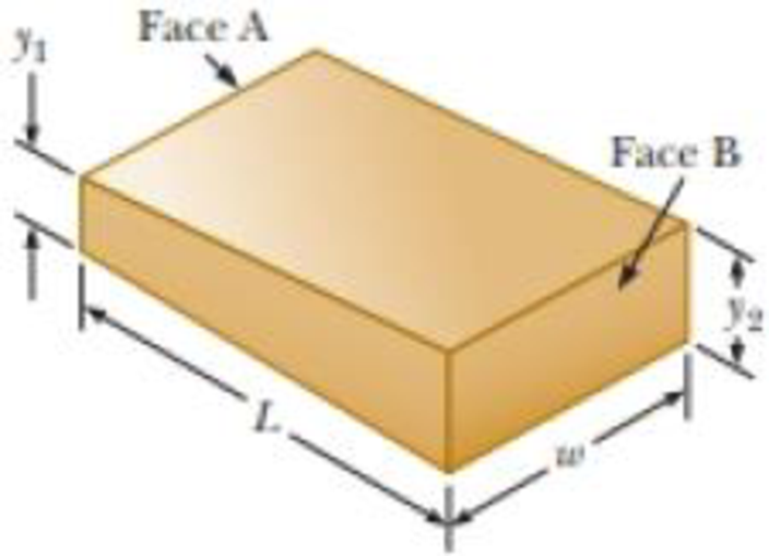
Material with uniform resistivity ρ is formed into a wedge as shown in Figure P26.50. Show that the resistance between face A and face B of this wedge is
Figure P26.50

Trending nowThis is a popular solution!

Chapter 26 Solutions
Physics for Scientists and Engineers with Modern Physics
Additional Science Textbook Solutions
Campbell Biology (11th Edition)
Laboratory Experiments in Microbiology (12th Edition) (What's New in Microbiology)
Human Physiology: An Integrated Approach (8th Edition)
HUMAN ANATOMY
Principles of Anatomy and Physiology


- You pour a litre (1 kg) of 25.0˚C water into a 0.500 kg aluminium pan off the stove, but has previously been heated so it starts with a temperature of 120˚C. What is the temperature when the water and the pan reach thermal equilibrium (i.e., what is the temperature of both objects when they reach the same temperature)? Assume that the pan is placed on an insulated pad and a negligible amount of water boils off.arrow_forwardA golf club hits a golf ball and the golf ball’s flight reaches a maximum height of 5.48 m. Calculate the momentum of the golf ball at the maximum height if the mass of the golf ball is 0.459 kg.arrow_forward• Superposition Theorem • Thevenin's and Norton's Theorem 1. Find the unknown voltage V₁, unknown resistances R1 and R2, and currents flowing through R1 and R2 for the circuit shown below using Superposition Theorem. 40 V + R₁₂ w B C ♥16A 10A www 4A F ww 2 E Ꭰ 2. Use Thevenin's Theorem to find the current flowing in 3-ohm resistor and its power dissipation from the circuit shown in the right. + 3. Use Norton's Theorem for the same instruction as for No. 2. 8 V A www 202 B wwww 20 Ω 10 V + 302 202 www C - 12 V 502 www.arrow_forward
- Fill in blanksarrow_forwardA rock is dropped from a height of 2.00 m. Determine the velocity of the rock just before it hits the ground. If the momentum of the rock just before hitting the ground is 14.0 kg m/s, what is the mass of the rock? Is the collision between the rock and the ground elastic or inelastic? Explain.arrow_forwardDescribe how the momentum of a single ball changes as it free falls from a height of approximately 1 m, collides with a hard floor, and rebounds.arrow_forward
- • Nature of Resistance Temperature-Resistance Relationship Ohm's Law, Energy and Power Kirchhoff's Law • • Maxwell's Mesh Analysis 1. The steel of the third rail of a railway system has a resistivity of 21.4 μ-cm. If its cross-sectional area is 8.2 in², calculate the resistance per mile of rail, neglecting the effect of joints between sections. (1 point) 2. An incandescent lamp has a tungsten filament whose resistance is 96 at its operating temperature of 2900°C. Calculate the filament resistance when the lamp is disconnected from the electric source, under which condition its temperature is 24°C. (Use do = 0.0045 02/°C for tungsten) (1 point) 3. For the circuit shown, find the following: 50 V 602 10 V 702 a. the value of resistor R. (1 point) b. the equivalent resistance with respect to the 50-V source. (1 point) 4. For the circuit shown, determine all the currents in each branch using Kirchhoff's Laws. (3 points) A 5V 2 В -ний C 4 6 VT ww F E 5. Use Maxwell's Mesh to find I, and VAB…arrow_forwardFor items 8-9, refer to the problem below. Find all the currents flowing in every resistor, power dissipation in every resistor and the total power of the circuit shown at the right using... 8. Kirchhoff's Laws (5 pts) 9. Maxwell's Mesh Analysis (5 pts) A 8 V 10 V B + 20 Ω 3Ω 202 wwww C wwww 202 + 50 www 12 Varrow_forward• Nature of Resistance Temperature-Resistance Relationship Ohm's Law, Energy and Power Kirchhoff's Law • Maxwell's Mesh Analysis 1. A coil of copper wire (p = 10.37 2-cmil/ft) has a length of 600 ft. What is the length of an aluminum conductor (p 17 cmil/ft), if its cross-sectional area and resistance are the same as those of the copper coil? (Hint: Look for conversion of inches to mils and square inches to square foot. Include it in your solution.) (1 pt) 2. The copper field winding of an electric machine has a resistance of 46 at temperature of 22°C. What will be its resistance at 75°C? (Use do = 0.00427 /°C for copper) (1 pt) 3. The resistivity of a copper rod 50 ft long and 0.25 inch in diameter is 1.76 μ at 20°C. What is its resistance at - 20°C? (1 pt) 4. When two resistors A and B are connected in series, the total resistance is 36 2. When connected in parallel, the total resistance is 8 Q. What is the ratio of the resistance RA to resistance RB? Assume RA < RB. (1 pt) 5. The…arrow_forward
- 2. Two equally strong individuals, wearing exactly the same shoes decide to do a tug of war. The only difference is individual A is 2.5 meters tall and individual B is 1.5 meter tall. Who is more likely to win the tug of war?arrow_forward6. A car drives at steady speed around a perfectly circular track. (a) The car's acceleration is zero. (b) The net force on the car is zero. (c) Both the acceleration and net force on the car point outward. (d) Both the acceleration and net force on the car point inward. (e) If there is no friction, the acceleration is outward.arrow_forward9. A spring has a force constant of 100 N/m and an unstretched length of 0.07 m. One end is attached to a post that is free to rotate in the center of a smooth. table, as shown in the top view in the figure below. The other end is attached to a 1kg disc moving in uniform circular motion on the table, which stretches the spring by 0.03 m. Friction is negligible. What is the centripetal force on the disc? Top View (a) 0.3 N (b) 3.0 N (c) 10 N (d) 300 N (e) 1000 Narrow_forward
 Physics for Scientists and EngineersPhysicsISBN:9781337553278Author:Raymond A. Serway, John W. JewettPublisher:Cengage Learning
 Physics for Scientists and Engineers with Modern ...PhysicsISBN:9781337553292Author:Raymond A. Serway, John W. JewettPublisher:Cengage Learning
 Principles of Physics: A Calculus-Based TextPhysicsISBN:9781133104261Author:Raymond A. Serway, John W. JewettPublisher:Cengage Learning
 Physics for Scientists and Engineers: Foundations...PhysicsISBN:9781133939146Author:Katz, Debora M.Publisher:Cengage Learning
 College PhysicsPhysicsISBN:9781305952300Author:Raymond A. Serway, Chris VuillePublisher:Cengage Learning