
Physics for Scientists and Engineers with Modern Physics
4th Edition
ISBN: 9780131495081
Author: Douglas C. Giancoli
Publisher: Addison-Wesley
expand_more
expand_more
format_list_bulleted
Concept explainers
Videos
Textbook Question
Chapter 26, Problem 31P
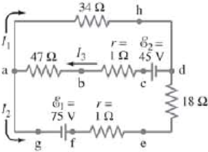
(II) (a) What is the potential difference between points a and d in Fig. 26–49 (similar to Fig. 26–13, Example 26–9), and (b) what is the terminal voltage of each battery?
FIGURE 26–49 Problem 31.
Expert Solution & Answer
Want to see the full answer?
Check out a sample textbook solution
Students have asked these similar questions
(II) Determine the terminal voltage of each battery in
Fig. 19–54.
r= 2.0 2
E = 18 V
R=4.8 2
r= 1.0 2
FIGURE 19-54
E = 12 V
Problem 26.
(III) Two resistors and two uncharged capacitors are arranged
as shown in Fig. 19–72. Then a potential difference of 24 V
is applied across the combination as shown. (a) What is the
potential at point a with switch S open? (Let V = 0 at the
negative terminal of the source.) (b) What is the potential at
point b with the switch
open? (c) When the
switch is closed, what
is the final potential of
point b? (d) How much +
charge flows through 24 V
8.8 N
0.48 μF
a
S
the switch S after it is
closed?
4.4 2
0.36 μF
FIGURE 19–72
Problem 58.
(II) If 21.0 V is applied across
the whole network of Fig. 19–63,
calculate (a) the voltage across
each capacitor and (b) the charge
on each capacitor.
C =
3.00 μF
C2 =
4.00 μF
C3 =
2.00 μF
FIGURE 19-63
V=
Problems 39 and 40.
-21.0 V-
Chapter 26 Solutions
Physics for Scientists and Engineers with Modern Physics
Ch. 26.1 - Repeat Example 261 assuming now that the...Ch. 26.2 - You have a 10- and a 15- resistor. What is the...Ch. 26.3 - Write the equation for the lower loop abcdefga of...Ch. 26.4 - If the jumper cables of Example 2610 were...Ch. 26.5 - In 10 times constants, the charge on the capacitor...Ch. 26 - Explain why birds can sit on power lines safely,...Ch. 26 - Discuss the advantages and disadvantages of...Ch. 26 - If all you have is a 120-V line, would it be...Ch. 26 - Two lightbulbs of resistance R1 and R2 (R2 R1)...Ch. 26 - Household outlets are often double outlets. Are...
Ch. 26 - With two identical lightbulbs and two identical...Ch. 26 - If two identical resistors are connected in series...Ch. 26 - You have a single 60-W bulb on in your room. How...Ch. 26 - When applying Kirchhoffs loop rule (such as in...Ch. 26 - Compare and discuss the formulas for resistors and...Ch. 26 - For what use are batteries connected in series?...Ch. 26 - Can the terminal voltage of a battery ever exceed...Ch. 26 - Explain in detail how you could measure the...Ch. 26 - In an RC circuit, current flows from the battery...Ch. 26 - Given the circuit shown in Fig. 2634, use the...Ch. 26 - Figure 2635 is a diagram of a capacitor (or...Ch. 26 - Design a circuit in which two different switches...Ch. 26 - What is the main difference between an analog...Ch. 26 - What would happen if you mistakenly used an...Ch. 26 - Explain why an ideal ammeter would have zero...Ch. 26 - A voltmeter connected across a resistor always...Ch. 26 - A small battery-operated flashlight requires a...Ch. 26 - Different lamps might have batteries connected in...Ch. 26 - Prob. 1PCh. 26 - (I) Four 1.50-V cells are connected in series to a...Ch. 26 - (II) A 1.5-V dry cell can be tested by connecting...Ch. 26 - (II) What is the internal resistance of a 12.0-V...Ch. 26 - (I) A 650- and a 2200- resistor are connected in...Ch. 26 - (I) Three 45- lightbulbs and three 65- lightbulbs...Ch. 26 - (I) Suppose that you have a 680-, a 720-, and a...Ch. 26 - (I) How many 10- resistors must be connected in...Ch. 26 - (II) Suppose that you have a 9.0-V battery and you...Ch. 26 - Three 1.70-k resistors can be connected together...Ch. 26 - (II) A battery with an emf of 12.0 V shows a...Ch. 26 - (II) Eight identical bulbs are connected in series...Ch. 26 - (II) Eight bulbs are connected in parallel to a...Ch. 26 - (II) The performance of the starter circuit in an...Ch. 26 - (II) A close inspection of an electric circuit...Ch. 26 - (II) Determine (a) the equivalent resistance of...Ch. 26 - (II) A 75-W, 110-V bulb is connected in parallel...Ch. 26 - (II) (a) Determine the equivalent resistance of...Ch. 26 - (II) Whal is the net resistance of the circuit...Ch. 26 - (II) Calculate the current through each resistor...Ch. 26 - (II) The two terminals of a voltage source with...Ch. 26 - (II) Two resistors when connected in series to a...Ch. 26 - (III) Three equal resistors (R) are connected to a...Ch. 26 - (III) A 2.8-k and a 3.7-k resistor are connected...Ch. 26 - (III) Consider the network of resistors shown in...Ch. 26 - (III) You are designing a wire resistance heater...Ch. 26 - (I) Calculate the current in the circuit of Fig....Ch. 26 - (II) Determine the terminal voltage of each...Ch. 26 - (II) For the circuit shown in Fig. 2647, find the...Ch. 26 - (II) (a) A network of five equal resistors R is...Ch. 26 - (II) (a) What is the potential difference between...Ch. 26 - (II) Calculate the currents in each resistor of...Ch. 26 - (II) Determine the magnitudes and directions of...Ch. 26 - (II) Determine the magnitudes and directions of...Ch. 26 - (II) A voltage V is applied to n identical...Ch. 26 - (III) (a) Determine the currents I1, I2, and I3 in...Ch. 26 - (III) What would the current I1 be in Fig. 2653 if...Ch. 26 - (III) Determine the current through each of the...Ch. 26 - (III) If the 25- resistor in Fig. 2654 is shorted...Ch. 26 - (III) Twelve resistors, each of resistance R, are...Ch. 26 - (III) Determine the net resistance in Fig. 2656...Ch. 26 - (II) Suppose two batteries, with unequal emfs of...Ch. 26 - (I) Estimate the range of resistance needed to...Ch. 26 - (II) In Fig. 2658 (same as Fig. 2617a), the total...Ch. 26 - (II) Two 3.8-F capacitors, two 2.2-k resistors,...Ch. 26 - (II) How long does it take for the energy stored...Ch. 26 - (II) A parallel-plate capacitor is filled with a...Ch. 26 - (II) The RC circuit of Fig. 2659 (same as Fig....Ch. 26 - (II) Consider the circuit shown in Fig. 2660,...Ch. 26 - (III) Determine the time constant for charging the...Ch. 26 - (III) Two resistors and two uncharged capacitors...Ch. 26 - (III) Suppose the switch S in Fig. 2662 is closed....Ch. 26 - (I) An ammeter has a sensitivity of 35,00 /V. What...Ch. 26 - (I) What is the resistance of a voltmeter on the...Ch. 26 - (II) A galvanometer has a sensitivity of 45 k/V...Ch. 26 - (II) A galvanometer has an internal resistance of...Ch. 26 - (II) A particular digital meter is based on an...Ch. 26 - (II) A milliammeter reads 25 mA full scale. It...Ch. 26 - (II) A 45-V battery of negligible internal...Ch. 26 - (II) An ammeter whose internal resistance is 53 ...Ch. 26 - (II) A battery with E=12.0V and internal...Ch. 26 - (II) A 12.0-V battery (assume the internal...Ch. 26 - (III) Two 9.4-k resistors are placed in series and...Ch. 26 - (III) When the resistor R in Fig. 2664 is 35 , the...Ch. 26 - Suppose that you wish to apply a 0.25-V potential...Ch. 26 - A three-way lightbulb can produce 50 W, 100 W, or...Ch. 26 - Suppose you want to run some apparatus that is 65...Ch. 26 - For the circuit shown in Fig. 2618a, show that the...Ch. 26 - A heart pacemaker is designed to operate at 72...Ch. 26 - Prob. 70GPCh. 26 - A Wheatstone bridge is a type of bridge circuit...Ch. 26 - An unknown length of platinum wire 1.22 mm in...Ch. 26 - The internal resistance of a 1.35-V mercury cell...Ch. 26 - How many 12-W resistors, each of the same...Ch. 26 - A solar cell, 3.0 cm square, has an output of 350...Ch. 26 - A power supply has a fixed output voltage of 12.0...Ch. 26 - The current through the 4.0-k resistor in Fig....Ch. 26 - A battery produces 40.8 V when 7.40 A is drawn...Ch. 26 - In the circuit shown in Fig. 2668, the 33-...Ch. 26 - The current through the 20- resistor in Fig. 2669...Ch. 26 - (a) A voltmeter and an ammeter can be connected as...Ch. 26 - (a) What is the equivalent resistance of the...Ch. 26 - A flashlight bulb rated at 2.0 W and 3.0 V is...Ch. 26 - Some light-dimmer switches use a variable resistor...Ch. 26 - A potentiometer is a device to precisely measure...Ch. 26 - Electronic devices often use an RC circuit to...Ch. 26 - The circuit shown in Fig. 2676 is a primitive...Ch. 26 - Determine the current in each resistor of the...Ch. 26 - In the circuit shown in Fig. 2678, switch S is...Ch. 26 - Figure 2679 shows the circuit for a simple...Ch. 26 - Measurements made on circuits that contain large...Ch. 26 - A typical voltmeter has an internal resistance of...Ch. 26 - (II) An RC series circuit contains a resistor R =...
Additional Science Textbook Solutions
Find more solutions based on key concepts
5. If the vector has a magnitude of 25 m and makes an angle of 30° with the +x axis, the vector
has a magnitu...
College Physics (10th Edition)
6.14 You apply a constant force to a 380-kg car as the car travels 48.0 m in a direction that is 240.0° counte...
University Physics with Modern Physics (14th Edition)
Explain all answers clearly, with complete sentences and proper essay structure if needed. An asterisk (*) desi...
Cosmic Perspective Fundamentals
A solid sphere contains positive charge uniformly distributed throughout its volume. Is the potential at its ce...
Essential University Physics: Volume 2 (3rd Edition)
The pV-diagram of the Carnot cycle.
Sears And Zemansky's University Physics With Modern Physics
Description of Motion:
Tutorials in Introductory Physics
Knowledge Booster


Learn more about
Need a deep-dive on the concept behind this application? Look no further. Learn more about this topic, physics and related others by exploring similar questions and additional content below.Similar questions
- (I) Calculate the current in the circuit of Fig. 19–53, and show that the sum of all the r= 2.0 2 voltage changes around the circuit is zero. 9.0 V 9.5 Q FIGURE 19–53 Problem 25. 14.0 2arrow_forwardIn the circuit shown in Fig. 19–93, C¡ = 1.0 µF, C2 = 2.0 µF, C3 = 2.4 µF, and a voltage_ Vab = 24 V is applied across points a and b. After C, is fully charged, the switch is thrown to the right. What is the final charge and potential differ- ence on each capacitor? ao C2 FIGURE 19-93 C3 Problem 97. boarrow_forward(II) Suppose two batteries, with unequal emfs of 2.00 V and 3.00 V, are connected as shown in Fig. 19–62. If each internal resistance is r = 0.350 N, and R = 4.00 N, what is the voltage R= 4.00 2 E= 2.00 V across the resistor R? FIGURE 19–62 Problem 36. E = 3.00 v"arrow_forward
- (III) (a) Determine the currents I, 1,, and Iz in Fig. 19–61. Assume the internal resistance of each battery is r = 1.0 N. (b) What is the terminal voltage of the 6.0-V battery? 12.0 V 22 Ω 12 2 28 Ω |12.0 V 11Ω 16 2 FIGURE 19–61 Problems 34 and 35. 6.0 V I3 wwarrow_forward(II) What is the total amount of energy stored in a 12-V, 65 A.Hcar battery when it is fully charged?arrow_forward(II) What is the net resistance of the circuit connected to the battery in Fig. 19–50? R R C ww B ww R V R FIGURE 19-50 R A Problems 19 and 20. wwarrow_forward
- Given the circuit shown in Fig. 19–38, use the words "increases," "decreases," or "stays the same" to complete the following statements: (a) If R, increases, the potential difference between A and - Assume no resistance in O and E. (b) If R, increases, the potential difference between A and Assume O and E have resistance. E E (c) If R, increases, the voltage drop across R4 (d) If R2 decreases, the current through R1 (e) If R, decreases, the current through R6 (f) If R2 decreases, the current through R3 (g) If R5 increases, the voltage drop across R2 (h) If R5 increases, the voltage drop across R4 (i) If R2, R5, and R7 increase, E (r = 0) R4 R5 D R6 R2 R3 R7 В FIGURE 19-38 Question 16. R1 R2, R5, and R, are variable resistors (you can change their resistance), given the symbol -WW-. A Aarrow_forward(I) (a) Six 4.8µF capacitors are connected in parallel.What is the equivalent capacitance? (b) What is their equivalent capacitance if connected in series?arrow_forward(II) A battery for a proposed electric car is to have threehundred 3-V lithium ion cells connected such that the totalvoltage across all of the cells is 300 V. Describe a possibleconnection configuration (using series and parallel connections) that would meet these battery specifications.arrow_forward
- (II) A 4.5-V battery is connected to a bulb whose resistanceis 1.3 Ω How many electrons leave the battery per minute?arrow_forward(II) Design a “voltage divider” (see Example 19–3) thatwould provide one-fifth (0.20) of the battery voltage across R2Fig. 19–6. What is the ratio R1/R2arrow_forward(III) (a) Determine the currents I₁, 12, and I3 in Fig. 19–61. Assume the internal resistance of each battery is r = 1.0. (b) What is the terminal voltage of the 6.0-V battery? r WITH 12.0 V 22 Ω 12 Ω 28 Ω FIGURE 19-61 Problems 34 and 35. 12.0 V 112 r 16 Ω |_ 6.0 V 13arrow_forward
arrow_back_ios
SEE MORE QUESTIONS
arrow_forward_ios
Recommended textbooks for you
 College PhysicsPhysicsISBN:9781305952300Author:Raymond A. Serway, Chris VuillePublisher:Cengage Learning
 University Physics (14th Edition)PhysicsISBN:9780133969290Author:Hugh D. Young, Roger A. FreedmanPublisher:PEARSON
 Introduction To Quantum MechanicsPhysicsISBN:9781107189638Author:Griffiths, David J., Schroeter, Darrell F.Publisher:Cambridge University Press
 Physics for Scientists and EngineersPhysicsISBN:9781337553278Author:Raymond A. Serway, John W. JewettPublisher:Cengage Learning
 Lecture- Tutorials for Introductory AstronomyPhysicsISBN:9780321820464Author:Edward E. Prather, Tim P. Slater, Jeff P. Adams, Gina BrissendenPublisher:Addison-Wesley
 College Physics: A Strategic Approach (4th Editio...PhysicsISBN:9780134609034Author:Randall D. Knight (Professor Emeritus), Brian Jones, Stuart FieldPublisher:PEARSON
College Physics
Physics
ISBN:9781305952300
Author:Raymond A. Serway, Chris Vuille
Publisher:Cengage Learning
University Physics (14th Edition)
Physics
ISBN:9780133969290
Author:Hugh D. Young, Roger A. Freedman
Publisher:PEARSON
Introduction To Quantum Mechanics
Physics
ISBN:9781107189638
Author:Griffiths, David J., Schroeter, Darrell F.
Publisher:Cambridge University Press
Physics for Scientists and Engineers
Physics
ISBN:9781337553278
Author:Raymond A. Serway, John W. Jewett
Publisher:Cengage Learning
Lecture- Tutorials for Introductory Astronomy
Physics
ISBN:9780321820464
Author:Edward E. Prather, Tim P. Slater, Jeff P. Adams, Gina Brissenden
Publisher:Addison-Wesley
College Physics: A Strategic Approach (4th Editio...
Physics
ISBN:9780134609034
Author:Randall D. Knight (Professor Emeritus), Brian Jones, Stuart Field
Publisher:PEARSON
How To Solve Any Circuit Problem With Capacitors In Series and Parallel Combinations - Physics; Author: The Organic Chemistry Tutor;https://www.youtube.com/watch?v=a-gPuw6JsxQ;License: Standard YouTube License, CC-BY