
University Physics with Modern Physics (14th Edition)
14th Edition
ISBN: 9780321973610
Author: Hugh D. Young, Roger A. Freedman
Publisher: PEARSON
expand_more
expand_more
format_list_bulleted
Videos
Textbook Question
Chapter 26, Problem 26.12E
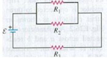
In Fig. E26.11 the battery has emf 35.0 V and negligible internal resistance. R1 = 5.00 Ω. The current through R1 is 1.50 A, and the current through R3 = 4.50A. What are the resistances R2 and R3?
Expert Solution & Answer

Learn your wayIncludes step-by-step video

schedule03:46
Students have asked these similar questions
Three resistors, R1 = 17.3, R2 = 13.2, R3 = 78, are connected in series across a 16.6 V battery. What is the voltage drop (in Volts) across R1?
A battery has emf 30.0 V and internal resistance r. A 9.00 Ω resistor is connected to the terminals of the battery, and the voltage drop across the resistor is 27.0 V. What is the internal resistance of the battery?
Two resistors, R1 = 21 Ω and R2 = 35 Ω are connected in parallel across a battery providing voltage ΔVbat = 5.7 V. What is the current through resistor R1?
Chapter 26 Solutions
University Physics with Modern Physics (14th Edition)
Ch. 26.1 - Suppose all three of the resistors shown in Fig....Ch. 26.2 - Subtract Eq. (1) from Eq. (2) in Example 26.6. To...Ch. 26.3 - You want to measure the current through and the...Ch. 26.4 - The energy stored in a capacitor is equal to...Ch. 26.5 - To prevent the circuit breaker in Example 26.14...Ch. 26 - In which 120-V light bulb does the filament have...Ch. 26 - Two 120-V light bulbs, one 25-W and one 200-W,...Ch. 26 - You connect a number of identical light bulbs to a...Ch. 26 - In the circuit shown in Fig. Q26.4, three...Ch. 26 - If two resistors R1 and R2 (R2 R1) are connected...
Ch. 26 - If two resistors R1 and R2 (R2 R1) are connected...Ch. 26 - A battery with no internal resistance is connected...Ch. 26 - A resistor consists of three identical metal...Ch. 26 - A light bulb is connected in the circuit shown in...Ch. 26 - A real battery, having nonnegligible internal...Ch. 26 - If the battery in Discussion Question Q26.10 is...Ch. 26 - Consider the circuit shown in Fig. Q26.12. What...Ch. 26 - Is it possible to connect resistors together in a...Ch. 26 - The battery in the circuit shown in Fig. Q26.14...Ch. 26 - In a two-cell flashlight, the batteries are...Ch. 26 - Identical light bulbs A, B, and C are connected as...Ch. 26 - The emf of a flashlight battery is roughly...Ch. 26 - Will the capacitors in the circuits shown in Fig....Ch. 26 - Verify that the time constant RC has units of...Ch. 26 - For very large resistances it is easy to construct...Ch. 26 - When a capacitor, battery, and resistor are...Ch. 26 - A uniform wire of resistance R is cut into three...Ch. 26 - A machine part has a resistor X protruding from an...Ch. 26 - A resistor with R1 = 25.0 is connected to a...Ch. 26 - A 42- resistor and a 20- resistor are connected in...Ch. 26 - A triangular array of resistors is shown in Fig....Ch. 26 - For the circuit shown in Fig. E26.6 both meters...Ch. 26 - For the circuit shown in Fig. E26.7 find the...Ch. 26 - Three resistors having resistances of 1.60 , 2.40...Ch. 26 - Now the three resistors of Exercise 26.8 are...Ch. 26 - Power Rating of a Resistor. The power rating of a...Ch. 26 - In Fig. E26.11, R1, = 3.00 , R2 = 6.00 , and R3=...Ch. 26 - In Fig. E26.11 the battery has emf 35.0 V and...Ch. 26 - Compute the equivalent resistance of the network...Ch. 26 - Compute the equivalent resistance of the network...Ch. 26 - In the circuit of Fig. E26.15, each resistor...Ch. 26 - Consider the circuit shown in Fig. E26.16. The...Ch. 26 - In the circuit shown in Fig. E26.17, the voltage...Ch. 26 - In the circuit shown in Fig. E26.18, = 36.0 V,...Ch. 26 - CP In the circuit in Fig. E26.19, a 20.0- resistor...Ch. 26 - In the circuit shown in Fig. E26.20, the rate at...Ch. 26 - Light Bulbs in Series and in Parallel. Two light...Ch. 26 - Light Bulbs in Series. A 60-W, 120-V light bulb...Ch. 26 - In the circuit shown in Fig. E26.23, ammeter A1...Ch. 26 - The batteries shown in the circuit in Fig. E26.24...Ch. 26 - In the circuit shown in Fig. E26.25 find (a) the...Ch. 26 - Find the emfs 1 and 2 in the circuit of Fig....Ch. 26 - In the circuit shown in Fig. E26.27, find (a) the...Ch. 26 - In the circuit shown in Fig. E26.28, find (a) the...Ch. 26 - The 10.00-V battery in Fig. E26.28 is removed from...Ch. 26 - The 5.00-V battery in Fig. E26.28 is removed from...Ch. 26 - In the circuit shown in Fig. E26.31 the batteries...Ch. 26 - In the circuit shown in Fig. E26.32 both batteries...Ch. 26 - In the circuit shown in Fig. E26.33 all meters are...Ch. 26 - In the circuit shown in Fig. E26.34, the 6.0-...Ch. 26 - The resistance of a galvanometer coil is 25.0 ,...Ch. 26 - The resistance of the coil of a pivoted coil...Ch. 26 - A circuit consists of a series combination of...Ch. 26 - A galvanometer having a resistance of 25.0 has a...Ch. 26 - A capacitor is charged to a potential of 12.0 V...Ch. 26 - You connect a battery, resistor, and capacitor as...Ch. 26 - A 4.60-F capacitor that is initially uncharged is...Ch. 26 - You connect a battery, resistor, and capacitor as...Ch. 26 - CP In the circuit shown in Fig. E26.43 both...Ch. 26 - A 12.4-F capacitor is connected through a 0.895-M...Ch. 26 - An emf source with = 120 V, a resistor with R =...Ch. 26 - A resistor and a capacitor are connected in series...Ch. 26 - CP In the circuit shown in Fig. E26.47 each...Ch. 26 - A 1.50-F capacitor is charging through a 12.0-...Ch. 26 - In the circuit in Fig. E26.49 the capacitors are...Ch. 26 - A 12.0-F capacitor is charged to a potential of...Ch. 26 - In the circuit shown in Fig. E26.51, C = 5.90 F, ...Ch. 26 - Prob. 26.52ECh. 26 - A 1500-W electric beater is plugged into the...Ch. 26 - In Fig. P26.54, the battery has negligible...Ch. 26 - The two identical light bulbs in Example 26.2...Ch. 26 - Each of the three resistors in Fig. P26.56 has a...Ch. 26 - (a) Find the potential of point a with respect to...Ch. 26 - CP For the circuit shown in Fig. P26.58 a 20.0-...Ch. 26 - Calculate the three currents I1, I2, and I3...Ch. 26 - What must the emf in Fig. P26.60 be in order for...Ch. 26 - Find the current through each of the three...Ch. 26 - (a) Find the current through the battery and each...Ch. 26 - Consider the circuit shown in Fig. P26.63. (a)...Ch. 26 - In the circuit shown in Fig. P26.64, = 24.0 V,...Ch. 26 - In the circuit shown in Fig. P26.65, the current...Ch. 26 - In the circuit shown in Fig. P26.66 all the...Ch. 26 - Figure P26.67 employs a convention often used in...Ch. 26 - Three identical resistors are connected in series....Ch. 26 - A resistor R1 consumes electrical power P1 when...Ch. 26 - The capacitor in Fig. F26.70 is initially...Ch. 26 - A 2.00-F capacitor that is initially uncharged is...Ch. 26 - A 6.00-F capacitor that is initially uncharged is...Ch. 26 - Point a in Fig. P26.73 is maintained at a constant...Ch. 26 - The Wheatstone Bridge. The circuit shown in Fig....Ch. 26 - (See Problem 26.67.) (a) What is the potential of...Ch. 26 - A 2.36-F capacitor that is initially uncharged is...Ch. 26 - A 224- resistor and a 589- resistor are connected...Ch. 26 - A resistor with R = 850 is connected to the...Ch. 26 - A capacitor that is initially uncharged is...Ch. 26 - DATA You set up the circuit shown in Fig. 26.22a,...Ch. 26 - DATA You set up the circuit shown in Fig. 26.20....Ch. 26 - DATA The electronics supply company where you work...Ch. 26 - An Infinite Network. As shown in Fig. P26.83, a...Ch. 26 - Suppose a resistor R lies along each edge of a...Ch. 26 - BIO Attenuator Chains and Axons. The infinite...Ch. 26 - Assume that a typical open ion channel spanning an...Ch. 26 - In a simple model of an axon conducting a nerve...Ch. 26 - Cell membranes across a wide variety of organisms...
Additional Science Textbook Solutions
Find more solutions based on key concepts
The pV-diagram of the Carnot cycle.
Sears And Zemansky's University Physics With Modern Physics
Choose the best answer to each of the following. Explain your reasoning. Which method could detect a planet in ...
Cosmic Perspective Fundamentals
27. A 25 kg child slides down a playground slide at a constant speed. The slide has a height of 3.0 m and is 7....
College Physics: A Strategic Approach (3rd Edition)
The circuits at right contain identical batteries and bulb. The boxes labeled X and Y representdifferent unknow...
Tutorials in Introductory Physics
A patient in an MRI unit turns his head quickly to one side and experiences momentary dizziness and a strange t...
College Physics
Q36.12 With which color of light can the Hubble Space Telescope see finer detail in a distant astronomical obje...
University Physics (14th Edition)
Knowledge Booster


Learn more about
Need a deep-dive on the concept behind this application? Look no further. Learn more about this topic, physics and related others by exploring similar questions and additional content below.Similar questions
- A 12.0-V emf automobile battery has a terminal voltage of 16.0 V when being charged by a current of 10.0 A. (a) What is the battery’s internal resistance? (b) What power is dissipated inside the battery? (c) At what rate (in °C/min ) will its temperature increase if its mass is 20.0 kg and it has a specific heat of 0.300 kcal/kg • °C, assuming no heat escapes?arrow_forwardThe emf source, E. of the circuit shown in the figure has negligible internal resistance. The resistors have resistances R= 6.62 and R,=4.92. The capacitor has a capacitance C 13.4 uF When the capacitor is fully charged, the magnitude of the charge on its plates is Q 17.1 uC. What is E in units of Volts? R2 O 4.4 O 2.2 R1 O 3.1 O 0.22 O 1.1arrow_forwardTwo resistors, R = 3.09 S and R2 = 5.27 2, are connected R1 in series to a battery with an EMF of 24.0 V and negligible internal resistance. Find the current I through R and the potential difference V across R2. I = A. R2 V2 = Varrow_forward
- N01arrow_forwardChapter 27, Problem 033 GO In the figure the current in resistance 6 is i6 = 1.47 A and the resistances are R₁ = R₂ = R3 = 1.75 2, R4 = 15.0, R5 = 8.83 What is the emf of the ideal battery? 66 E R₁ R₂ R₂ FWM T 8 FWM 8 www R R₁ Chapter 27, Problem 039 GO In the figure two batteries of emf E = 11.0 V and internal resistance r = 0.306 2 are connected in parallel across a resistance R. (a) For what value of R is the dissipation rate in the resistor a maximum? (b) What is that maximum? , and R6 = 3.55 9. 2. www R io Ro 16arrow_forwardA 400 µF capacitor is connected through a resistor to a battery. Find (a) the resistance R and (b) the emf of the battery if the time constant of the circuit is 0.5 s and the maximum charge on the capacitor is 0.024 C. O a. R = 1350 0, e = 80 V O b. R = 1250 0, E = 60 V O C. R = 1200 Q, e = 80 V O d. R = 1150 Q, e = 60 Varrow_forward
- In (Figure 1) the battery has emf 45.0 V and negligible internal resistance. R₁ = 7.00 2. The current through R₁ is 1.50 A and the current through R3 = 4.50 A. Figure ww R₁ www R₂ www- R₂ < 1 of 1 ▼ What is the resistance R₂? Express your answer with the appropriate units. R₂: Submit Part B R3 11 .0 Submit μA Value What is the resistance R3 ? Express your answer with the appropriate units. Request Answer HÅ Value Units Request Answer Units ?arrow_forwardA toy battery has an emf of 33.0 V. The terminal voltage of the battery is 15.50 V when it is delivering 30.50 W of power to an external load resistor R. What is the internal resistance ( in Q) of the battery? Round your answer to the nearest thousandth of Q.arrow_forwardThe drawing shows 3 resistors of R₁ = 28.00. R₂ = 46.0 02. R3 = 76.00. The current through resistor R3 is 13 = 0.530 A. What is the total voltage V the battery supplies? ww V + R₂ R3 ww 81.4 V 125 V 70.6 V 65.3 V 79.5 V wwwarrow_forward
- A heart pacemaker fires exactly 71 times a minute. Each time it fires, a 19.0 nF capacitor is charged by a battery in series with a resistor to 0.582 of its full voltage. What is the value of the resistance R?arrow_forwardTwo resistors, R1 = 50 Ω and R2 = 17 Ω are connected in series to a battery providing voltage ΔVbat = 3.1 V. What is the potential difference measured across the resistor R2?arrow_forward24.0 V 4.00 A R 4.00 A Figure N 8. Consider the circuit shown in Figure b. The terminal voltage of the 24.0 V battery is 21.2 V. What is a) the internal resistance r of the battery; b) the resistance R of the circuit resistor???arrow_forward
arrow_back_ios
SEE MORE QUESTIONS
arrow_forward_ios
Recommended textbooks for you

 Principles of Physics: A Calculus-Based TextPhysicsISBN:9781133104261Author:Raymond A. Serway, John W. JewettPublisher:Cengage Learning
Principles of Physics: A Calculus-Based Text
Physics
ISBN:9781133104261
Author:Raymond A. Serway, John W. Jewett
Publisher:Cengage Learning
DC Series circuits explained - The basics working principle; Author: The Engineering Mindset;https://www.youtube.com/watch?v=VV6tZ3Aqfuc;License: Standard YouTube License, CC-BY