Fundamentals of Physics Extended
10th Edition
ISBN: 9781118230725
Author: David Halliday, Robert Resnick, Jearl Walker
Publisher: Wiley, John & Sons, Incorporated
expand_more
expand_more
format_list_bulleted
Concept explainers
Videos
Textbook Question
Chapter 25, Problem 39P
Go In Fig. 25-45, C1 = 10.0 μF, C2= 20.0 μF, and C3 = 25.0 μF. If no capacitor can withstand a potential difference of more than 100 V without failure, what are (a) the magnitude of the maximum potential difference that can exist between points A and B and (b) the maximum energy that can be stored in the three-capacitor arrangement?
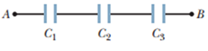
Figure 25-45 Problem 39.
Expert Solution & Answer
Want to see the full answer?
Check out a sample textbook solution
Students have asked these similar questions
How can you tell which vowel is being produced here ( “ee,” “ah,” or “oo”)? Also, how would you be able to tell for the other vowels?
You want to fabricate a soft microfluidic chip like the one below. How would you go about
fabricating this chip knowing that you are targeting a channel with a square cross-sectional
profile of 200 μm by 200 μm. What materials and steps would you use and why? Disregard the
process to form the inlet and outlet.
Square Cross Section
1. What are the key steps involved in the fabrication of a semiconductor device.
2. You are hired by a chip manufacturing company, and you are asked to prepare a silicon wafer
with the pattern below. Describe the process you would use.
High Aspect
Ratio
Trenches
Undoped Si Wafer
P-doped Si
3. You would like to deposit material within a high aspect ratio trench. What approach would you
use and why?
4. A person is setting up a small clean room space to carry out an outreach activity to educate high
school students about patterning using photolithography. They obtained a positive photoresist, a
used spin coater, a high energy light lamp for exposure and ordered a plastic transparency mask
with a pattern on it to reduce cost. Upon trying this set up multiple times they find that the full
resist gets developed, and they are unable to transfer the pattern onto the resist. Help them
troubleshoot and find out why pattern of transfer has not been successful.
5. You are given a composite…
Chapter 25 Solutions
Fundamentals of Physics Extended
Ch. 25 - Figure 25-18 shows plots of charge versus...Ch. 25 - What is Ceq of three capacitors, each of...Ch. 25 - a In Fig. 25-19a are capacitors 1 and 3 in series?...Ch. 25 - Figure 25-20 shows three circuits, each consisting...Ch. 25 - Initially, a single capacitance C1 is wired to a...Ch. 25 - Repeat Question 5 for C2 added in series rather...Ch. 25 - For each circuit in Fig. 25-21, are the capacitors...Ch. 25 - Figure 25-22 shows an open switch, a battery of...Ch. 25 - A parallel-plate capacitor is connected to a...Ch. 25 - When a dielectric slab is inserted between the...
Ch. 25 - You are to connect capacitances C1 and C2, with...Ch. 25 - The two metal objects in Fig. 25-24 have net...Ch. 25 - The capacitor in Fig. 25-25 has a capacitance of...Ch. 25 - SSM A parallel-plate capacitor has circular plates...Ch. 25 - The plates of spherical capacitor have radii 38.0...Ch. 25 - What is the capacitance of a drop that results...Ch. 25 - You have two flat metal plates, each of area...Ch. 25 - If an uncharged parallel-plate capacitor...Ch. 25 - How many 1.00 F capacitors must be connected in...Ch. 25 - Each of the uncharged capacitors in Fig. 25-27 has...Ch. 25 - In Fig. 25-28, find the equivalent capacitance of...Ch. 25 - In Fig. 25-29, find the equivalent capacitance of...Ch. 25 - Two parallel-plate capacitors, 6.0 F each, are...Ch. 25 - SSM ILW A 100 pF capacitor is charged to a...Ch. 25 - GO In Fig. 25-30, the battery has a potential...Ch. 25 - GO In Fig. 25-31, a 20.0 V battery is connected...Ch. 25 - Plot in Fig. 25-32a gives the charge q that can be...Ch. 25 - GO In Fig. 25-29, a potential difference of V =...Ch. 25 - Figure 25-33 shows a circuit section of four...Ch. 25 - GO In Fig. 25-34, the battery has potential...Ch. 25 - Figure 25-35 shows a variable "airgap capacitor...Ch. 25 - SSM WWWIn Fig. 25-36, capacitances are charged C1...Ch. 25 - In Fig. 25-37, V = 10 V, C1 = 10 F, and C2 = C3 =...Ch. 25 - The capacitors in Fig. 25-38 are initially...Ch. 25 - GO Figure 25-39 represents two air-filled...Ch. 25 - GO In Fig. 25-40, two parallel-plate capacitors...Ch. 25 - GO Capacitor 3 in Fig. 25-41a is a variable...Ch. 25 - GO Figure 25-42 shows a 12.0 V battery and four...Ch. 25 - GO Figure 25-43 displays a 12.0 V battery and 3...Ch. 25 - What capacitance is required to store an energy of...Ch. 25 - How much energy is stored in 1.00 m3of air due to...Ch. 25 - SSMA 2.0 F capacitor and a 4.0 F capacitor are...Ch. 25 - A parallel-plate air-filled capacitor having area...Ch. 25 - A charged isolated metal sphere of diameter 10 cm...Ch. 25 - In Fig. 25-28, a potential difference V = 100 V is...Ch. 25 - Assume that a stationary electron is a point of...Ch. 25 - As a safety engineer, you must evaluate the...Ch. 25 - SSM ILW WWW The parallel plates in a capacitor,...Ch. 25 - In Fig. 25-29, a potential difference V = 100 V is...Ch. 25 - Go In Fig. 25-45, C1 = 10.0 F, C2= 20.0 F, and C3...Ch. 25 - An air-filled parallel-plate capacitor has a...Ch. 25 - SSMA coaxial cable used in a transmission line has...Ch. 25 - A parallel-plate air-filled capacitor has a...Ch. 25 - Given a 7.4 pF air-filled capacitor, you are asked...Ch. 25 - You are asked to construct a capacitor having a...Ch. 25 - A certain parallel-plate capacitor is filled with...Ch. 25 - In Fig. 25-46, how much charge is stored on the...Ch. 25 - SSM ILWA certain substance has a dielectric...Ch. 25 - Figure 25-47 shows a parallel-plate capacitor with...Ch. 25 - Figure 25-48 shows a parallel-plate capacitor with...Ch. 25 - Go Figure 25-49 shows a parallel-plate capacitor...Ch. 25 - SSM WWWA parallel-plate capacitor has a...Ch. 25 - For the arrangement of Fig. 25-17, suppose that...Ch. 25 - A parallel-plate capacitor has plates of area 0.12...Ch. 25 - Two parallel plates of area 100 cm2 are given...Ch. 25 - The space between two concentric conducting...Ch. 25 - In Fig. 25-50, the battery potential difference V...Ch. 25 - SSMIn Fig. 25-51, V = 9.0 V, C1 = C2= 30 F, and C3...Ch. 25 - a If C = 50 F in Fig. 25-52, what is the...Ch. 25 - In Fig.25-53, V = 12 V, C1 = C4 = 2.0 F, C2 = 4.0...Ch. 25 - The chocolate crumb mystery. This troy begins with...Ch. 25 - Figure 25-54 shows capacitor 1 C1 = 8.00 F,...Ch. 25 - Two air-filled, parallel-plate capacitors are to...Ch. 25 - Two parallel-plate capacitors, 6.0 F each, are...Ch. 25 - GO In Fig. 25-55, V = 12 V, C1 = C5 = C6 = 6.0 F,...Ch. 25 - SSM In Fig.25-56, the parallel-plate capacitor of...Ch. 25 - A cylindrical capacitor has radii a and b as in...Ch. 25 - A capacitor of capacitance C1 = 6.00 F is...Ch. 25 - Repeat Problem 67 for the same two capacitors but...Ch. 25 - A certain capacitor is charged to a potential...Ch. 25 - Aslab of copper of thickness b = 2.00 mm is thrust...Ch. 25 - Repeat Problem 70, assuming that a potential...Ch. 25 - A potential difference of 300 V is applied to a...Ch. 25 - Figure 25-58 shows a four capacitor arrangement...Ch. 25 - You have two plates of copper, a sheet of mica...Ch. 25 - A capacitor of unknown capacitance Cis charged to...Ch. 25 - A 10 V battery is connected to a series of n...Ch. 25 - SSM In Fig. 25-59, two parallel-plate capacitors A...Ch. 25 - You have many 2.0F capacitors, each capable of...Ch. 25 - A parallel-plate capacitor has charge q and plate...Ch. 25 - A capacitor is charged until its stored energy is...
Additional Science Textbook Solutions
Find more solutions based on key concepts
Pure oxygen gas can be prepared in the laboratory by the decomposition of solid potassium chlorate to form soli...
Introductory Chemistry (6th Edition)
31. A weather balloon rises through the atmosphere, its volume expanding from 4.0 m3 to 12 m3 as the temperatur...
College Physics: A Strategic Approach (3rd Edition)
Where is each type of membrane located in the body? What are their functions?
Principles of Anatomy and Physiology
Draw the mechanism for the reaction of cyclohexene with HCl.
Organic Chemistry (8th Edition)
Two culture media were inoculated with four different bacteria. After incubation, the following results were ob...
Microbiology: An Introduction
3. Is the particle in FIGURE Q1.3 speeding up? Slowing down? Or can you tell? Explain.
FIGURE Q1.3
Physics for Scientists and Engineers: A Strategic Approach, Vol. 1 (Chs 1-21) (4th Edition)
Knowledge Booster


Learn more about
Need a deep-dive on the concept behind this application? Look no further. Learn more about this topic, physics and related others by exploring similar questions and additional content below.Similar questions
- Two complex values are z1=8 + 8i, z2=15 + 7 i. z1∗ and z2∗ are the complex conjugate values. Any complex value can be expessed in the form of a+bi=reiθ. Find r and θ for (z1-z∗2)/z1+z2∗. Find r and θ for (z1−z2∗)z1z2∗ Please show all stepsarrow_forwardAn electromagnetic wave is traveling through vacuum in the positive x direction. Its electric field vector is given by E=E0sin(kx−ωt)j^,where j^ is the unit vector in the y direction. If B0 is the amplitude of the magnetic field vector, find the complete expression for the magnetic field vector B→ of the wave. What is the Poynting vector S(x,t), that is, the power per unit area associated with the electromagnetic wave described in the problem introduction? Give your answer in terms of some or all of the variables E0, B0, k, x, ω, t, and μ0. Specify the direction of the Poynting vector using the unit vectors i^, j^, and k^ as appropriate. Please explain all stepsarrow_forwardAnother worker is performing a task with an RWL of only 9 kg and is lifting 18 kg, giving him an LI of 2.0 (high risk). Questions:What is the primary issue according to NIOSH?Name two factors of the RWL that could be improved to reduce risk.If the horizontal distance is reduced from 50 cm to 30 cm, how does the HM change and what effect would it have?arrow_forward
- Two complex values are z1=8 + 8i, z2=15 + 7 i. z1∗ and z2∗ are the complex conjugate values. Any complex value can be expessed in the form of a+bi=reiθ. Find r and θ for z1z2∗. Find r and θ for z1/z2∗? Find r and θ for (z1−z2)∗/z1+z2∗. Find r and θ for (z1−z2)∗/z1z2∗ Please explain all steps, Thank youarrow_forwardAn ac series circuit consists of a voltage source of frequency 60 Hz and voltage amplitude V, a 505-Ω resistor, and a capacitor of capacitance 7.2 μF. What must be the source voltage amplitude V for the average electrical power consumed in the resistor to be 236 W? There is no inductance in the circuit.arrow_forwardAn L−R−C series circuit has R= 280 Ω . At the frequency of the source, the inductor has reactance XLL= 905 Ω and the capacitor has reactance XC= 485 Ω . The amplitude of the voltage across the inductor is 445 V . What is the amplitude of the voltage across the resistor and the capacitor? What is the voltage amplitude of the source? What is the rate at which the source is delivering electrical energy to the circuit?arrow_forward
- A 0.185 H inductor is connected in series with a 98.5 Ω resistor and an ac source. The voltage across the inductor is vL=−(12.5V)sin[(476rad/s)t]vL. Derive an expression for the voltage vR across the resistor. Express your answer in terms of the variables L, R, VL (amplitude of the voltage across the inductor), ω, and t. What is vR at 2.13 ms ? Please explain all stepsarrow_forwardA worker lifts a box under the following conditions:Horizontal distance (H): 30 cmInitial height (V): 60 cmVertical travel (D): 50 cmTorso rotation (A): 30°Frequency: 3 times/minute for 1 hourGrip: Good Question:What is the RWL for this task?What does this value mean in terms of occupational safety?arrow_forwardCan someone helparrow_forward
- Can someone help mearrow_forward3. Four identical small masses are connected in a flat perfect square. Rank the relative rotational inertias (IA, IB, IC) about the three axes of rotation shown. Axes A and B are in the plane of the square, and axis C is perpendicular to the plane, through mass m1. ΙΑ IB m2 m1 m3 Ic m4 (a) IAarrow_forwardConsider the circuit shown in the figure below. (Assume L = 5.20 m and R2 = 440 Ω.) (a) When the switch is in position a, for what value of R1 will the circuit have a time constant of 15.4 µs? (b) What is the current in the inductor at the instant the switch is thrown to position b?arrow_forwardarrow_back_iosSEE MORE QUESTIONSarrow_forward_ios
Recommended textbooks for you
 Principles of Physics: A Calculus-Based TextPhysicsISBN:9781133104261Author:Raymond A. Serway, John W. JewettPublisher:Cengage Learning
 Physics for Scientists and Engineers, Technology ...PhysicsISBN:9781305116399Author:Raymond A. Serway, John W. JewettPublisher:Cengage Learning
 College PhysicsPhysicsISBN:9781285737027Author:Raymond A. Serway, Chris VuillePublisher:Cengage Learning
 Physics for Scientists and EngineersPhysicsISBN:9781337553278Author:Raymond A. Serway, John W. JewettPublisher:Cengage Learning
 Physics for Scientists and Engineers with Modern ...PhysicsISBN:9781337553292Author:Raymond A. Serway, John W. JewettPublisher:Cengage Learning
Principles of Physics: A Calculus-Based Text
Physics
ISBN:9781133104261
Author:Raymond A. Serway, John W. Jewett
Publisher:Cengage Learning
Physics for Scientists and Engineers, Technology ...
Physics
ISBN:9781305116399
Author:Raymond A. Serway, John W. Jewett
Publisher:Cengage Learning
College Physics
Physics
ISBN:9781285737027
Author:Raymond A. Serway, Chris Vuille
Publisher:Cengage Learning
Physics for Scientists and Engineers
Physics
ISBN:9781337553278
Author:Raymond A. Serway, John W. Jewett
Publisher:Cengage Learning
Physics for Scientists and Engineers with Modern ...
Physics
ISBN:9781337553292
Author:Raymond A. Serway, John W. Jewett
Publisher:Cengage Learning
Physics Capacitor & Capacitance part 7 (Parallel Plate capacitor) CBSE class 12; Author: LearnoHub - Class 11, 12;https://www.youtube.com/watch?v=JoW6UstbZ7Y;License: Standard YouTube License, CC-BY