
VEC MECH 180-DAT EBOOK ACCESS(STAT+DYNA)
12th Edition
ISBN: 9781260916942
Author: BEER
Publisher: MCG
expand_more
expand_more
format_list_bulleted
Videos
Textbook Question
Chapter 2.5, Problem 2.111P
A transmission tower is held by three guy wires attached to a pin at A and anchored by bolts at B, C, and D. If the tension in wire AB is 840 lb, determine the vertical force P exerted by the tower on the pin at A.
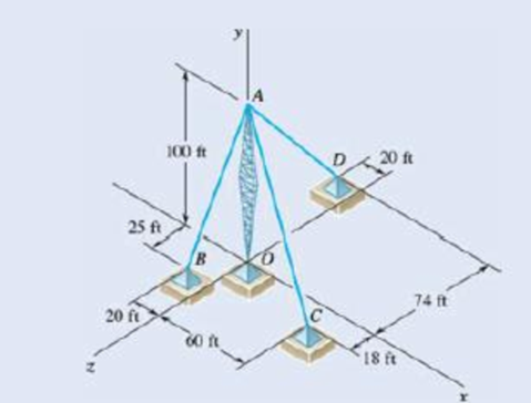
Fig. P2.111 and P2.112
Expert Solution & Answer
Want to see the full answer?
Check out a sample textbook solution
Students have asked these similar questions
I REPEAT!!!!! I NEED HANDDRAWING!!!!! NOT A USELESS EXPLANATION!!!! I REPEAT SUBMIT A HANDDRAWING IF YOU CANNOT UNDERSTAND THIS SKIP IT !
I need the real handdrawing complete it by adding these :
Pneumatic Valves
Each linear actuator must be controlled by a directional control valve (DCV) (e.g., 5/2 or 4/2 valve).
The bi-directional motor requires a reversible valve to change rotation direction.
Pressure Regulators & Air Supply
Include two pressure regulators as per the assignment requirement.
Show the main compressed air supply line connecting all components.
Limit Switches & Safety Features
Attach limit switches to each actuator to detect positions.
Implement a two-handed push-button safety system to control actuator movement.
Connections Between Components
Draw air supply lines linking the compressor, valves, and actuators.
Clearly label all inputs and outputs for better understanding.
An elastic bar of the length L and cross section area A is rigidly attached
to the ceiling of a room, and it supports a mass M. Due to the
acceleration of gravity g the rod deforms vertically. The deformation of
the rod is measured by the vertical displacement u(x) governed by the
following equations:
dx
(σ(x)) + b(x) = 0
PDE
σ(x) = Edx
du
Hooke's law
(1)
b(x) = gp=
body force per unit volume
where E is the constant Young's modulus, p is the density, and σ(x) the
axial stress in the rod.
g
* I u(x)
L
2
Chapter 2 Solutions
VEC MECH 180-DAT EBOOK ACCESS(STAT+DYNA)
Ch. 2.1 - Two forces are applied as shown to a hook....Ch. 2.1 - Two forces are applied as shown to a bracket...Ch. 2.1 - Two forces P and Q are applied as shown at point A...Ch. 2.1 - Two forces P and Q are applied as shown at point A...Ch. 2.1 - A stake is being pulled out of the ground by means...Ch. 2.1 - A telephone cable is clamped at A to the pole AB....Ch. 2.1 - A telephone cable is clamped at A to the pole AB....Ch. 2.1 - A disabled automobile is pulled by means of two...Ch. 2.1 - A disabled automobile is pulled by means of two...Ch. 2.1 - Two forces are applied as shown to a hook support....
Ch. 2.1 - A steel tank is to be positioned in an excavation....Ch. 2.1 - A steel tank is to be positioned in an excavation....Ch. 2.1 - A steel tank is to be positioned in an excavation....Ch. 2.1 - For the hook support of Prob. 2.10, determine by...Ch. 2.1 - The barge B is pulled by two tugboats A and C. At...Ch. 2.1 - Solve Prob. 2.1 by trigonometry.Ch. 2.1 - Solve Prob. 2.4 by trigonometry.Ch. 2.1 - For the stake of Prob. 2.5, knowing that the...Ch. 2.1 - Two structural members A and B are bolted to a...Ch. 2.1 - Two structural members A and B are bolted to a...Ch. 2.2 - Determine the x and y components of each of the...Ch. 2.2 - Determine the x and y components of each of die...Ch. 2.2 - Determine the x and y components of each of the...Ch. 2.2 - Determine the x and y components of each of the...Ch. 2.2 - Member BC exerts on member AC a force P directed...Ch. 2.2 - Member BD exerts on member ABC a force P directed...Ch. 2.2 - Prob. 2.27PCh. 2.2 - Cable AC exerts on beam AD a force P directed...Ch. 2.2 - The hydraulic cylinder BD exerts on member ABC a...Ch. 2.2 - The guy wire BD exerts on the telephone pole AC a...Ch. 2.2 - Determine the resultant of the three forces of...Ch. 2.2 - Determine the resultant of the three forces of...Ch. 2.2 - Determine the resultant of the three forces of...Ch. 2.2 - Determine the resultant of the three forces of...Ch. 2.2 - Knowing that = 35, determine the resultant of the...Ch. 2.2 - Knowing that the tension in cable BC is 725 N,...Ch. 2.2 - Knowing that = 40, determine the resultant of the...Ch. 2.2 - Knowing that = 75, determine the resultant of the...Ch. 2.2 - PROBLEM 2.39 A collar that can slide on a vertical...Ch. 2.2 - PROBLEM 2.40 For the beam of Problem 2.36,...Ch. 2.2 - PROBLEM 2.41 Determine (a) the required tension in...Ch. 2.2 - PROBLEM 2.42 For the block of Problems 2.37 and...Ch. 2.3 - Two cables are tied together at C and loaded as...Ch. 2.3 - Two forces of magnitude TA = 8 kips and TB = 15...Ch. 2.3 - The 60-lb collar A can slide on a frictionless...Ch. 2.3 - A chairlift has been stopped in the position...Ch. 2.3 - Two cables are tied together at C and are loaded...Ch. 2.3 - Two cables are tied together at C and are loaded...Ch. 2.3 - Two cables are tied together at C and loaded as...Ch. 2.3 - Two cables are tied together at C and are loaded...Ch. 2.3 - Prob. 2.47PCh. 2.3 - Knowing that = 20, determine the tension (a) in...Ch. 2.3 - Two cables are tied together at C and are loaded...Ch. 2.3 - Two cables are tied together at C and are loaded...Ch. 2.3 - Prob. 2.51PCh. 2.3 - Two forces P and Q are applied as shown to an...Ch. 2.3 - A welded connection is in equilibrium under the...Ch. 2.3 - A welded connection is in equilibrium under the...Ch. 2.3 - A sailor is being rescued using a boatswains chair...Ch. 2.3 - A sailor is being rescued using a boatswains chair...Ch. 2.3 - For the cables of Prob. 2.44, find the value of ...Ch. 2.3 - For the cables of Prob. 2.46, it is known that the...Ch. 2.3 - For the situation described in Fig. P2.48,...Ch. 2.3 - Two cables tied together at C are loaded as shown....Ch. 2.3 - A movable bin and its contents have a combined...Ch. 2.3 - Prob. 2.62PCh. 2.3 - Collar A is connected as shown to a 50-lb load and...Ch. 2.3 - Collar A is connected as shown to a 50-lb load and...Ch. 2.3 - A cable loop of length 1.5 m is placed around a...Ch. 2.3 - A 200-kg crate is to be supported by the...Ch. 2.3 - A 600-lb crate is supported by several...Ch. 2.3 - Solve parts b and d of Prob. 2.67, assuming that...Ch. 2.3 - A load Q is applied to the pulley C, which can...Ch. 2.3 - An 1800-N load Q is applied to pulley C, which can...Ch. 2.4 - Determine (a) the x, y, and z components of the...Ch. 2.4 - Determine (a) the x, y, and z components of the...Ch. 2.4 - A gun is aimed at a point A located 35 east of...Ch. 2.4 - Solve Prob. 2.73 assuming that point A is located...Ch. 2.4 - The angle between the guy wire AB and the mast is...Ch. 2.4 - The angle between the guy wire AC and the mast is...Ch. 2.4 - Cable AB is 65 ft long, and the tension in that...Ch. 2.4 - PROBLEM 2.78 Cable AC is 70 ft long, and the...Ch. 2.4 - Determine the magnitude and direction of the force...Ch. 2.4 - Determine the magnitude and direction of the force...Ch. 2.4 - Prob. 2.81PCh. 2.4 - Prob. 2.82PCh. 2.4 - Prob. 2.83PCh. 2.4 - A force acts at the origin of a coordinate system...Ch. 2.4 - Two cables BG and BH are attached to frame ACD as...Ch. 2.4 - Two cables BG and BH are attached to frame ACD as...Ch. 2.4 - In order to move a wrecked truck, two cables are...Ch. 2.4 - In order to move a wrecked truck, two cables are...Ch. 2.4 - A rectangular plate is supported by three cables...Ch. 2.4 - A rectangular plate is supported by three cables...Ch. 2.4 - Find the magnitude and direction of the resultant...Ch. 2.4 - Prob. 2.92PCh. 2.4 - Knowing that the tension is 425 lb in cable AB and...Ch. 2.4 - Knowing that the tension is 510 lb in cable AB and...Ch. 2.4 - Prob. 2.95PCh. 2.4 - Prob. 2.96PCh. 2.4 - The boom OA carries a load P and is supported by...Ch. 2.4 - Fig. P2.97 2.98 For the boom and loading of Prob....Ch. 2.5 - Three cables are used to tether a balloon as...Ch. 2.5 - A container of mass m = 120 kg is supported by...Ch. 2.5 - A 150-lb cylinder is supported by two cables AC...Ch. 2.5 - A transmission tower is held by three guy wires...Ch. 2.5 - A container is supported by three cables that are...Ch. 2.5 - A container is supported by three cables that are...Ch. 2.5 - Three cables are used to tether a balloon as...Ch. 2.5 - Three cables are used to tether a balloon as...Ch. 2.5 - A crate is supported by three cables as shown....Ch. 2.5 - A crate is supported by three cables as shown....Ch. 2.5 - A 12-lb circular plate of 7-in. radius is...Ch. 2.5 - Solve Prob. 2.105, knowing that = 45.Ch. 2.5 - Three cables are connected at A, where the forces...Ch. 2.5 - Fig. P2.107 and P2.108 2.108 Three cables are...Ch. 2.5 - Prob. 2.109PCh. 2.5 - A rectangular plate is supported by three cables...Ch. 2.5 - A transmission tower is held by three guy wires...Ch. 2.5 - A transmission tower is held by three guy wires...Ch. 2.5 - In trying to move across a slippery icy surface, a...Ch. 2.5 - Fig. P2.113 2.114 Solve Prob. 2.113 assuming that...Ch. 2.5 - For the rectangular plate of Probs. 2.109 and...Ch. 2.5 - PROBLEM 2.116 For the cable system of Problems...Ch. 2.5 - PROBLEM 2.117 For the cable system of Problems...Ch. 2.5 - Three cables are connected at D, where an upward...Ch. 2.5 - For the transmission tower of Probs. 2.111 and...Ch. 2.5 - Three wires are connected at point D, which is...Ch. 2.5 - A container of weight W is suspended from ring A,...Ch. 2.5 - Prob. 2.122PCh. 2.5 - A container of weight W is suspended from ring A....Ch. 2.5 - Prob. 2.124PCh. 2.5 - Fig. P2.113 2.114 Solve Prob. 2.113 assuming that...Ch. 2.5 - Prob. 2.126PCh. 2 - Two forces P and Q are applied to the lid of a...Ch. 2 - Determine the x and y components of each of the...Ch. 2 - A hoist trolley is subjected to the three forces...Ch. 2 - Knowing that = 55 and that boom AC exerts on pin...Ch. 2 - Two cables are tied together at C and loaded as...Ch. 2 - Two cables tied together at C are loaded as shown....Ch. 2 - The end of the coaxial cable AE is attached to the...Ch. 2 - Prob. 2.134RPCh. 2 - Find the magnitude and direction of the resultant...Ch. 2 - Cable BAC passes through a frictionless ring A and...Ch. 2 - Collars A and B are connected by a 25-in.-lang...Ch. 2 - Fig. P2.137 and P2.138 2.138 Collars A and B are...
Knowledge Booster


Learn more about
Need a deep-dive on the concept behind this application? Look no further. Learn more about this topic, mechanical-engineering and related others by exploring similar questions and additional content below.Similar questions
- An elastic bar of the length L and cross section area A is rigidly attached to the ceiling of a room, and it supports a mass M. Due to the acceleration of gravity g the rod deforms vertically. The deformation of the rod is measured by the vertical displacement u(x) governed by the following equations: dx (σ(x)) + b(x) = 0 PDE σ(x) = Edx du Hooke's law (1) b(x) = gp= body force per unit volume where E is the constant Young's modulus, p is the density, and σ(x) the axial stress in the rod. g * I u(x) L 2arrow_forwardمتوسعة الفرج بو عمامة المستوى رم الواجب المنزلي رقم 04 تمرین الوان حسب يتمعن العبارات الأتية : A= (+2)+(-45) B=(+13)- C = (+17)-(+13)-(-20)+(-19 D= [(-15)-(+15)]-[(+20) + هست قیم مدرج مبدؤه النقطة ة الطول :tcm A(-2,5): B(+ 2,5) ≤ C (+5) المسافتين : BAD ين الثاني لمستوي مبدؤه 8 وحدتهarrow_forwardPlease do not rely too much on AI, because its answer may be wrong. Please consider it carefully and give your own answer!!!!! You can borrow ideas from AI, but please do not believe its answer.Very very grateful! ( If you write by hand or don't use AI, I'll give you a big thumbs up ) Please do not copy other's work,i will be very very grateful!!Please do not copy other's work,i will be very very grateful!!arrow_forward
- A thin uniform rod of mass m and length 2r rests in a smooth hemispherical bowl of radius r. A moment M = mgr horizontal plane. is applied to the rod. Assume that the bowl is fixed and its rim is in the HINT: It will help you to find the length l of that portion of the rod that remains outside the bowl. M 2r Ꮎ a) How many degrees of freedom does this system have? b) Write an equation for the virtual work in terms of the angle 0 and the motion of the center of mass (TF) c) Derive an equation for the variation in the position of the center of mass (i.e., Sŕƒ) a. HINT: Use the center of the bowl as the coordinate system origin for the problem. d) In the case of no applied moment (i.e., M = 0), derive an equation that can be used to solve for the equilibrium angle of the rod. DO NOT solve the equation e) In the case of an applied moment (i.e., M: = mgr 4 -) derive an equation that can be used to solve for the equilibrium angle of the rod. DO NOT solve the equation. f) Can the angle 0 and…arrow_forwardSolve this problem and show all of the workarrow_forwardSolve this problem and show all of the workarrow_forward
- Solve this problem and show all of the workarrow_forwardPlease do not rely too much on chatgpt, because its answer may be wrong. Please consider it carefully and give your own answer. You can borrow ideas from gpt, but please do not believe its answer.Very very grateful! Please do not copy other's work,i will be very very grateful!!Please do not copy other's work,i will be very very grateful!!arrow_forward= The frame shown is fitted with three 50 cm diameter frictionless pulleys. A force of F = 630 N is applied to the rope at an angle ◊ 43°. Member ABCD is attached to the wall by a fixed support at A. Find the forces indicated below. Note: The rope is tangent to the pully (D) and not secured at the 3 o'clock position. a b •C *су G E e d BY NC SA 2013 Michael Swanbom Values for dimensions on the figure are given in the following table. Note the figure may not be to scale. Variable Value a 81 cm b 50 cm с 59 cm d 155 cm For all answers, take x as positive to the right and positive upward. At point A, the fixed support exerts a force of: A = + ĴN and a reaction couple of: →> ΜΑ Member CG is in Select an answer magnitude У as k N-m. and carries a force of N.arrow_forward
- The lower jaw AB [Purple 1] and the upper jaw-handle AD [Yellow 2] exert vertical clamping forces on the object at R. The hand squeezes the upper jaw-handle AD [2] and the lower handle BC [Orane 4] with forces F. (Member CD [Red 3] acts as if it is pinned at D, but, in a real vise-grips, its position is actually adjustable.) The clamping force, R, depends on the geometry and on the squeezing force F applied to the handles. Determine the proportionality between the clamping force, R, and the squeezing force F for the dimensions given. d3 d4 R 1 B d1 2 d2 D... d5 F 4 F Values for dimensions on the figure are given in the following table. Note the figure may not be to scale. Variable Value d1 65 mm d2 156 mm d3 50 mm 45 d4 d5 113 mm 30 mm R = Farrow_forwardA triangular distributed load of max intensity w =460 N/m acts on beam AB. The beam is supported by a pin at A and member CD, which is connected by pins at C and D respectively. Determine the reaction forces at A and C. Enter your answers in Cartesian components. Assume the masses of both beam AB and member CD are negligible. cc 040 BY NC SA 2016 Eric Davishahl W A C D -a- B Ул -b- x Values for dimensions on the figure are given in the following table. Note the figure may not be to scale. Variable Value α 5.4 m b 8.64 m C 3.24 m The reaction at A is A = i+ ĴN. λ = i+ Ĵ N. The reaction at C is C =arrow_forward56 Clamps like the one shown are commonly used in woodworking applications. This clamp has the dimensions given in the table below the figure, and its jaws are mm thick (in the direction perpendicular to the plane of the picture). a.) The screws of the clamp are adjusted so that there is a uniform pressure of P = 150 kPa being applied to the workpieces by the jaws. Determine the force carried in each screw. Hint: the uniform pressure can be modeled in 2-D as a uniform distributed load with intensity w = Pt (units of N/m) acting over the length of contact between the jaw and the workpiece. b.) Determine the minimum vertical force (parallel to the jaws) required to pull either one of the workpieces out of the clamp jaws. Use a coefficient of static friction between all contacting surfaces of μs = 0.56 and the same clamping pressure given for part (a). 2013 Michael Swanbom A B C a Values for dimensions on the figure are given in the following table. Note the figure may not be to scale.…arrow_forward
arrow_back_ios
SEE MORE QUESTIONS
arrow_forward_ios
Recommended textbooks for you
 Elements Of ElectromagneticsMechanical EngineeringISBN:9780190698614Author:Sadiku, Matthew N. O.Publisher:Oxford University Press
 Mechanics of Materials (10th Edition)Mechanical EngineeringISBN:9780134319650Author:Russell C. HibbelerPublisher:PEARSON
 Thermodynamics: An Engineering ApproachMechanical EngineeringISBN:9781259822674Author:Yunus A. Cengel Dr., Michael A. BolesPublisher:McGraw-Hill Education
 Control Systems EngineeringMechanical EngineeringISBN:9781118170519Author:Norman S. NisePublisher:WILEY
 Mechanics of Materials (MindTap Course List)Mechanical EngineeringISBN:9781337093347Author:Barry J. Goodno, James M. GerePublisher:Cengage Learning
 Engineering Mechanics: StaticsMechanical EngineeringISBN:9781118807330Author:James L. Meriam, L. G. Kraige, J. N. BoltonPublisher:WILEY
Elements Of Electromagnetics
Mechanical Engineering
ISBN:9780190698614
Author:Sadiku, Matthew N. O.
Publisher:Oxford University Press
Mechanics of Materials (10th Edition)
Mechanical Engineering
ISBN:9780134319650
Author:Russell C. Hibbeler
Publisher:PEARSON
Thermodynamics: An Engineering Approach
Mechanical Engineering
ISBN:9781259822674
Author:Yunus A. Cengel Dr., Michael A. Boles
Publisher:McGraw-Hill Education
Control Systems Engineering
Mechanical Engineering
ISBN:9781118170519
Author:Norman S. Nise
Publisher:WILEY
Mechanics of Materials (MindTap Course List)
Mechanical Engineering
ISBN:9781337093347
Author:Barry J. Goodno, James M. Gere
Publisher:Cengage Learning
Engineering Mechanics: Statics
Mechanical Engineering
ISBN:9781118807330
Author:James L. Meriam, L. G. Kraige, J. N. Bolton
Publisher:WILEY
Physics 33 - Fluid Statics (1 of 10) Pressure in a Fluid; Author: Michel van Biezen;https://www.youtube.com/watch?v=mzjlAla3H1Q;License: Standard YouTube License, CC-BY