Figure 24.49 shows a small plant near a thin lens. The ray shown Is one of the principal rays for the lens. Each square is 2.0 cm along the horizontal direction, but the vertical direction is not to the same scale. Use information from the diagram to answer the following questions: (a) Using only the ray shown, decide what type of lens (converging or diverging) this is. (b) What is the focal length of the lens? (c) Locate the image by drawing the other two principal rays. (d) Calculate where the image should be, and compare this result with the graphical solution in part (c). Figure 24.49 Problem 50.
Figure 24.49 shows a small plant near a thin lens. The ray shown Is one of the principal rays for the lens. Each square is 2.0 cm along the horizontal direction, but the vertical direction is not to the same scale. Use information from the diagram to answer the following questions: (a) Using only the ray shown, decide what type of lens (converging or diverging) this is. (b) What is the focal length of the lens? (c) Locate the image by drawing the other two principal rays. (d) Calculate where the image should be, and compare this result with the graphical solution in part (c). Figure 24.49 Problem 50.
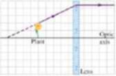
Figure 24.49 shows a small plant near a thin lens. The ray shown Is one of the principal rays for the lens. Each square is 2.0 cm along the horizontal direction, but the vertical direction is not to the same scale. Use information from the diagram to answer the following questions: (a) Using only the ray shown, decide what type of lens (converging or diverging) this is. (b) What is the focal length of the lens? (c) Locate the image by drawing the other two principal rays. (d) Calculate where the image should be, and compare this result with the graphical solution in part (c).
(a) The graph below was produced from the data of a thin lens. By analyzing it, what can we saysay about its characteristics, i.e., convergence/divergence and focal length? Explain your reasoning.(b) A thin lens is used to project an image onto a screen. If we cover the right half of the lens,what happens to the projected image? Explain.
Problem 8: Consider the compound optical system shown in the diagram, where two thin lenses of focal lengths 7.5 cm (left lens) and 7.5 cm (right lens) are separated by a distance 45 cm.
a. If an object is placed a distance do = 17.3 cm to the left of the first lens (the left one) as shown in the figure, how far to the right of that lens, in centimeters, is the image formed?
b. What is the magnification of the first lens?
c. What is the object distance, in centimeters, for the second lens (the right lens)?
d. What is the image distance, in centimeters, for the second lens?
e. What is the magnification of the second lens?
Shown in the figure below is a system containing two lenses and an object. The focal lengths of the two lenses are f, = 17 cm and f, = -8.5 cm. The two lengths indicated in the figure are L, = 25.5 cm and L, = 13.6 cm.
f1
f2
L2
Determine all the following about the image from the first lens only:
Object distance for the first lens, doi-
x cm
Image distance for the first lens, d.
cm
Magnification of the first lens, m,.
The second lens uses the image from the first lens as its object. Determine all the following about the image from the second lens:
Object distance for the second lens, dos-
cm
Image distance for the second lens, d.
cm
Magnification of the second lens, m.
Determine the magnification of the whole system, mtot-
Select the correct attributes of the final image of the system:
O real
O virtual
O shrunk
O enlarged
O right side up
O upside down
NOTE: Throughout the problem be careful with the sign of every quantity.
Physics for Scientists and Engineers with Modern Physics
Knowledge Booster
Learn more about
Need a deep-dive on the concept behind this application? Look no further. Learn more about this topic, physics and related others by exploring similar questions and additional content below.


 Physics for Scientists and Engineers: Foundations...PhysicsISBN:9781133939146Author:Katz, Debora M.Publisher:Cengage Learning
 University Physics Volume 3PhysicsISBN:9781938168185Author:William Moebs, Jeff SannyPublisher:OpenStax
 Glencoe Physics: Principles and Problems, Student...PhysicsISBN:9780078807213Author:Paul W. ZitzewitzPublisher:Glencoe/McGraw-Hill