Concept explainers
(a)
The current induced in the aluminum ring
(a)
Answer to Problem 5P
A current of
Explanation of Solution
Write the equation for the emf generated in the coil.
Here,
Here,
Write the equation for the magnetic field due to the solenoid.
Here,
Substitute
Write the equation for the area of the coil.
Here,
Substitute equation (VI) in equation (V).
The ring is placed at one end of a solenoid. The field in the end of the solenoid is half the field at the center of the solenoid. Write the equation for the emf induced in the ring.
Substitute
Write the equation for the current induced in the ring.
Conclusion:
Substitute
Therefore, the current induced in the ring is
(b)
The magnitude of magnetic field in the ring
(b)
Answer to Problem 5P
The induced current produces a magnetic field of
Explanation of Solution
Write the equation for the magnetic field produced in the ring.
Here,
Conclusion:
Substitute
Therefore, the induced current produces a magnetic field of
(c)
The direction of magnetic field in the ring
(c)
Answer to Problem 5P
The magnetic field in the ring points towards the left
Explanation of Solution
Figure (I) shows the direction of the magnetic field in the solenoid.
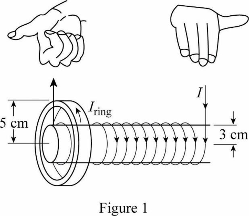
The magnetic field of the solenoid points to the right as shown in figure.1. Therefore, the magnetic field at the center of the ring acts towards the left in order to oppose the increasing field.
Conclusion:
Therefore, the magnetic field in the ring acts towards the left.
Want to see more full solutions like this?
Chapter 23 Solutions
Principles of Physics: A Calculus-Based Text


- Hi! I need help with these calculations for part i and part k for a physics Diffraction Lab. We used a slit width 0.4 mm to measure our pattern.arrow_forwardExamine the data and % error values in Data Table 3 where the angular displacement of the simple pendulum decreased but the mass of the pendulum bob and the length of the pendulum remained constant. Describe whether or not your data shows that the period of the pendulum depends on the angular displacement of the pendulum bob, to within a reasonable percent error.arrow_forwardIn addition to the anyalysis of the graph, show mathematically that the slope of that line is 2π/√g . Using the slope of your line calculate the value of g and compare it to 9.8.arrow_forward
- An object is placed 24.1 cm to the left of a diverging lens (f = -6.51 cm). A concave mirror (f= 14.8 cm) is placed 30.2 cm to the right of the lens to form an image of the first image formed by the lens. Find the final image distance, measured relative to the mirror. (b) Is the final image real or virtual? (c) Is the final image upright or inverted with respect to the original object?arrow_forwardConcept Simulation 26.4 provides the option of exploring the ray diagram that applies to this problem. The distance between an object and its image formed by a diverging lens is 5.90 cm. The focal length of the lens is -2.60 cm. Find (a) the image distance and (b) the object distance.arrow_forwardPls help ASAParrow_forward
 Principles of Physics: A Calculus-Based TextPhysicsISBN:9781133104261Author:Raymond A. Serway, John W. JewettPublisher:Cengage Learning
 Physics for Scientists and Engineers with Modern ...PhysicsISBN:9781337553292Author:Raymond A. Serway, John W. JewettPublisher:Cengage Learning
 Physics for Scientists and EngineersPhysicsISBN:9781337553278Author:Raymond A. Serway, John W. JewettPublisher:Cengage Learning
 Physics for Scientists and Engineers: Foundations...PhysicsISBN:9781133939146Author:Katz, Debora M.Publisher:Cengage Learning
 Physics for Scientists and Engineers, Technology ...PhysicsISBN:9781305116399Author:Raymond A. Serway, John W. JewettPublisher:Cengage Learning