
Fundamentals of Electric Circuits
6th Edition
ISBN: 9780078028229
Author: Charles K Alexander, Matthew Sadiku
Publisher: McGraw-Hill Education
expand_more
expand_more
format_list_bulleted
Concept explainers
Videos
Textbook Question
Chapter 2.3, Problem 4PP
How many branches and nodes does the circuit in Fig. 2.14 have? Identify the elements that are in series and in parallel.
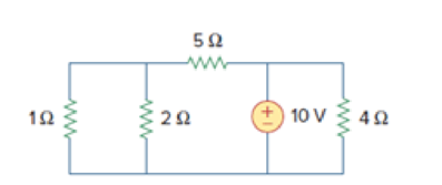
Figure 2.14
For Practice Prob. 2.4.
Expert Solution & Answer
Want to see the full answer?
Check out a sample textbook solution
Students have asked these similar questions
Sketch the output of the analogue computer shown below and find its closest
describing function [suppose any variable to find the DF]
+1
ew2
HI
e2
1.0 +21
LO
SJ
eo
SJ
ew
LO
1.0 +|e1|
HI
-1
ew1 ek(1 + e。)
|e1|
k =
1+|e1|
Figure V-5
Feedback Limiter Behavior
ROUNDED, DUE TO DIODE
NONLINEARITY
LIMIT VOLTAGE
409
DIODE CONDUCTS
First, write the output transaction, then draw the output wave, and then find the
Describing function. I need to solve the question step by step, with an explanation
of each step.
Sketch the output of the analogue computer shown below and find its closest
describing function [suppose any variable to find the DF]
SJ
ew2
ew₁
HI
|e2|
2
LO
1.0 +21
LO
-1
HI
Jel
1.0+|e1|
ROUNDED, DUE TO DODE
NONLINEARITY
LIMIT VOLTAGE
DIODE CONDUCTS
ew1e, -k(1+ e。)
k
=
|e1|
1+|e1|
Figure 1-5 Feedback Limiter Behavior
First, write the output transaction, then draw the output wave, and then find the
Describing function. I need to solve the question step by step, with an explanation
of each step.
Sketch the output of the analogue computer shown below and find its closest
describing function [suppose any variable to find the DF]
SJ
+1
HI
LO
e2
1.0 +21
ew2
eo
SJ
ew₁
LO
Jel
1.0 +|e1|
HI
-1
ew1 ek(1+eo)
k =
|e1|
1+|e1|
First, write the output transaction, then draw the output wave, and then find the
Describing function. I need to solve the question step by step, with an explanation
of each step.
Chapter 2 Solutions
Fundamentals of Electric Circuits
Ch. 2.2 - The essential component of a toaster is an...Ch. 2.2 - For the circuit shown in Fig. 2.9, calculate the...Ch. 2.2 - A resistor absorbs an instantaneous power of 30...Ch. 2.3 - How many branches and nodes does the circuit in...Ch. 2.4 - Find v1 and v2 in the circuit of Fig. 2.22. Figure...Ch. 2.4 - Find vx and vo in the circuit of Fig. 2.24. Figure...Ch. 2.4 - Find vo and io in the circuit of Fig. 2.26. Figure...Ch. 2.4 - Find the current and voltages in the circuit shown...Ch. 2.6 - By combining the resistors in Fig.2.36, find Req....Ch. 2.6 - Find Rab for the circuit in Fig.2.39. Figure 2.39...
Ch. 2.6 - Calculate Geq in the circuit of Fig.2.41. Figure...Ch. 2.6 - Find v1 and v2 in the circuit shown in Fig. 2.43....Ch. 2.7 - Transform the wye network in Fig. 2.51 to a delta...Ch. 2.7 - For the bridge network in Fig. 2.54, find Rab and...Ch. 2.8 - Refer to Fig. 2.55 and assume there are six light...Ch. 2.8 - Following the ammeter setup of Fig. 2.61. design...Ch. 2 - The reciprocal of resistance is: (a) voltage (b)...Ch. 2 - Prob. 2RQCh. 2 - Prob. 3RQCh. 2 - The maximum current that a 2W, 80 k resistor can...Ch. 2 - Prob. 5RQCh. 2 - The current I in the circuit of Fig. 2.63 is: (a)...Ch. 2 - The current I0 of Fig. 2.64 is: (a) 4 A (b) 2 A...Ch. 2 - In the circuit in Fig. 2.65, V is: (a) 30 V (b) 14...Ch. 2 - Which of the circuit in Fig. 2.66 will give you...Ch. 2 - In the circuit of Fig. 2.67, a decrease in R3...Ch. 2 - Design a problem, complete with a solution, to...Ch. 2 - Find the hot resistance of a light bulb rated 60...Ch. 2 - A bar of silicon is 4 cm long with a circular...Ch. 2 - (a) Calculate current i in Fig. 2.68 when the...Ch. 2 - For the network graph in Fig. 2.69. find the...Ch. 2 - In the network graph shown in Fig. 2.70, determine...Ch. 2 - Determine the number of branches and nodes in the...Ch. 2 - Design a problem, complete with a solution, to...Ch. 2 - Find i1, i2, and i3 in Fig. 2.73. Figure 2.73 For...Ch. 2 - Determine i1 and i2 in the circuit of Fig. 2.74....Ch. 2 - In the circuit of Fig. 2.75, calculate V1 and V2....Ch. 2 - In the circuit in Fig. 2.76, obtain v1, v2, and...Ch. 2 - For the circuit in Fig. 2.77, use KCL to find the...Ch. 2 - Given the circuit in Fig. 2.78, use KVL to find...Ch. 2 - Calculate v and ix in the circuit of Fig. 2.79....Ch. 2 - Determine Vo in the circuit in Fig. 2.80. Figure...Ch. 2 - Obtain v1 through v3 in the circuit of Fig. 2.81....Ch. 2 - Find I and V in the circuit of Fig. 2.82. Figure...Ch. 2 - From the circuit in Fig. 2.83, find I, the power...Ch. 2 - Determine io in the circuit of Fig. 2.84. Figure...Ch. 2 - Find Vx in the circuit of Fig. 2.85. Figure 2.85...Ch. 2 - Find Vo in the circuit in Fig. 2.86 and the power...Ch. 2 - In the circuit shown in Fig. 2.87, determine Vx...Ch. 2 - For the circuit in Fig. 2.88, find Vo/Vs in terms...Ch. 2 - For the network in Fig. 2.89, find the current,...Ch. 2 - For the circuit in Fig. 2.90, io = 3 A. Calculate...Ch. 2 - Calculate Io in the circuit of Fig. 2.91. Figure...Ch. 2 - Design a problem, using Fig. 2.92, to help other...Ch. 2 - All resistors (R) in Fig. 2.93 are 10 each. Find...Ch. 2 - For the circuit in Fig. 2.95, determine i1 to i5....Ch. 2 - Find i1 through i4 in the circuit in Fig. 2.96....Ch. 2 - Obtain v and i in the circuit of Fig. 2.97. Figure...Ch. 2 - Using series/parallel resistance combination, find...Ch. 2 - Calculate Vo and Io in the circuit of Fig. 2.99....Ch. 2 - Find i and Vo in the circuit of Fig. 2.100. Figure...Ch. 2 - Given the circuit in Fig. 2.101 and that the...Ch. 2 - Find Req and io in the circuit of Fig. 2.102....Ch. 2 - Evaluate Req looking into each set of terminals...Ch. 2 - For the ladder network in Fig. 2.104, find I and...Ch. 2 - If Req = 50 in the circuit of Fig. 2.105, find R....Ch. 2 - Reduce each of the circuits in Fig. 2.106 to a...Ch. 2 - Calculate the equivalent resistance Rab at...Ch. 2 - For the circuits in Fig. 2.108, obtain the...Ch. 2 - Find the equivalent resistance at terminals a-b of...Ch. 2 - Find I in the circuit of Fig. 2.110. Figure 2.110Ch. 2 - Find the equivalent resistance Rab in the circuit...Ch. 2 - Convert the circuits in Fig. 2.112 from Y to ....Ch. 2 - Transform the circuits in Fig. 2.113 from to Y....Ch. 2 - Design a problem to help other students better...Ch. 2 - Obtain the equivalent resistance at the terminals...Ch. 2 - For the circuit shown in Fig. 2.116, find the...Ch. 2 - Obtain the equivalent resistance Rab in each of...Ch. 2 - Consider the circuit in Fig. 2.118. Find the...Ch. 2 - Calculate I0 in the circuit of Fig. 2.119. Figure...Ch. 2 - Determine V in the circuit of Fig. 2.120. Figure...Ch. 2 - Find Req and I in the circuit of Fig. 2.121....Ch. 2 - The 150 W tight bulb in Fig. 2.122 is rated at 110...Ch. 2 - If the three bulbs of Prob. 2.59 are connected in...Ch. 2 - As a design engineer, you are asked to design a...Ch. 2 - Prob. 62PCh. 2 - If an ammeter with an internal resistance of 100 ...Ch. 2 - The potentiometer (adjustable resistor) Rx in Fig....Ch. 2 - Design a circuit that uses a dArsonval meter (with...Ch. 2 - A 20-k/V voltmeter reads 10 V full scale. (a) What...Ch. 2 - (a) Obtain the voltage Vo in the circuit of Fig....Ch. 2 - (a) Find the current I in the circuit of Fig....Ch. 2 - A voltmeter used to measure Vo in the circuit in...Ch. 2 - (a) Consider the Wheatstone bridge shown in Fig....Ch. 2 - Figure 2.131 represents a model of a solar...Ch. 2 - Find Vo in the two-way power divider circuit in...Ch. 2 - An ammeter model consists of an ideal ammeter in...Ch. 2 - The circuit in Fig. 2.134 is to control the speed...Ch. 2 - Find Rab in the four-way power divider circuit in...Ch. 2 - Repeat Prob. 2.75 for the eight-way divider shown...Ch. 2 - Suppose your circuit laboratory has the following...Ch. 2 - In the circuit in Fig. 2.137, the wiper divides...Ch. 2 - Prob. 79CPCh. 2 - A loudspeaker is connected to an amplifier as...Ch. 2 - For a specific application, the circuit shown in...Ch. 2 - The pin diagram of a resistance array is shown in...Ch. 2 - Two delicate devices are rated as shown in Fig....
Knowledge Booster


Learn more about
Need a deep-dive on the concept behind this application? Look no further. Learn more about this topic, electrical-engineering and related others by exploring similar questions and additional content below.Similar questions
- Can you help me find the result of an integral 0/2 a² X + a dxarrow_forwardQ1/Sketch the root locus for the system shown in Figure 1 and find the following: a. The exact point and gain where the locus crosses the jo-axis b. The breakaway point on the real axis c. The range of K within which the system is stable d. Angles of departure and arrival R(s) + K(s²-4s +20) C(s) (s+2)(s + 4)arrow_forwardExam2 Subject: (Numerical Analysis) Class: Third Date: 27/4/2025 Time: 60 minutes Q1. For what values of k does this system of equations has no solution? (use Gauss-Jordan eliminations) kx + y + z = 1 x+ky + z = 1 x+y+kz=1arrow_forward
- Consider the Difference equation of a causal Linear time-invariant (LTI) system given by: (y(n) - 1.5y(n - 1) + 0.5y(n = 2) = x(n) a) Implement the difference equation model of this system. b) Find the system transfer function H(z). c) For an input x(n) = 8(n), determine the output response y(n). d) Verify the initial value theorem y(0) with part (c).arrow_forwardQ5B. Find the type of the controller in the following figures and use real values to find the transfer function of three of them[ Hint Pi,Pd and Lead,lag are found so put the controller with its corresponding compensator]. R₁ R₂ Rz HE C2 RA HE R₁ R2 RA とarrow_forwardQ1// Sketch the root locus for the unity feedback system. Where G(s)=)= K S3+252 +25 and find the following a. Sketch the asymptotes b. The exact point and gain where the locus crosses the jo-axis c. The breakaway point on the real axis d. The range of K within which the system is stable e. Angles of departure and arrival.arrow_forward
- Determine X(w) for the given function shown in Figure (1) by applying the differentiation property of the Fourier Transform. Figure (1) -1 x(t)arrow_forwardCan you solve a question with a drawing Determine X(w) for the given function shown in Figure (1) by applying the differentiation property of the Fourier Transform. Figure (1) -1 x(t)arrow_forwardAn inductor has a current flow of 3 A when connected to a 240 V, 60 Hz power line. The inductor has a wire resistance of 15 Find the Q of the inductorarrow_forward
- صورة من s94850121arrow_forwardThe joint density function of two continuous random variables X and Yis: p(x, y) = {Keós (x + y) Find (i) the constant K 0 2 0arrow_forwardShow all the steps please, Solve for the current through R2 if E2 is replaced by a current source of 10mA using superposition theorem. R5=470Ω R2=1000Ω R6=820Ωarrow_forwardarrow_back_iosSEE MORE QUESTIONSarrow_forward_ios
Recommended textbooks for you
 Introductory Circuit Analysis (13th Edition)Electrical EngineeringISBN:9780133923605Author:Robert L. BoylestadPublisher:PEARSON
 Delmar's Standard Textbook Of ElectricityElectrical EngineeringISBN:9781337900348Author:Stephen L. HermanPublisher:Cengage Learning
 Programmable Logic ControllersElectrical EngineeringISBN:9780073373843Author:Frank D. PetruzellaPublisher:McGraw-Hill Education
 Fundamentals of Electric CircuitsElectrical EngineeringISBN:9780078028229Author:Charles K Alexander, Matthew SadikuPublisher:McGraw-Hill Education
 Electric Circuits. (11th Edition)Electrical EngineeringISBN:9780134746968Author:James W. Nilsson, Susan RiedelPublisher:PEARSON
 Engineering ElectromagneticsElectrical EngineeringISBN:9780078028151Author:Hayt, William H. (william Hart), Jr, BUCK, John A.Publisher:Mcgraw-hill Education,
Introductory Circuit Analysis (13th Edition)
Electrical Engineering
ISBN:9780133923605
Author:Robert L. Boylestad
Publisher:PEARSON
Delmar's Standard Textbook Of Electricity
Electrical Engineering
ISBN:9781337900348
Author:Stephen L. Herman
Publisher:Cengage Learning
Programmable Logic Controllers
Electrical Engineering
ISBN:9780073373843
Author:Frank D. Petruzella
Publisher:McGraw-Hill Education
Fundamentals of Electric Circuits
Electrical Engineering
ISBN:9780078028229
Author:Charles K Alexander, Matthew Sadiku
Publisher:McGraw-Hill Education
Electric Circuits. (11th Edition)
Electrical Engineering
ISBN:9780134746968
Author:James W. Nilsson, Susan Riedel
Publisher:PEARSON
Engineering Electromagnetics
Electrical Engineering
ISBN:9780078028151
Author:Hayt, William H. (william Hart), Jr, BUCK, John A.
Publisher:Mcgraw-hill Education,
Thevenin's Theorem; Author: Neso Academy;https://www.youtube.com/watch?v=veAFVTIpKyM;License: Standard YouTube License, CC-BY