
Concept explainers
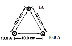
The required current in the top wire in the given figure to produce a field of zero at the point equidistant from the wires, provided currents in the bottom two wires are both 10.0 A into the page.
Answer to Problem 71PE
Explanation of Solution
Given:
Current carrying wire is placed at the vertices of an equilateral triangle of side 10.0 cm=
Formula used:
Magnetic field due to a long current carrying wire at perpendicular distance
Where
Calculation:
Label the wires at the vertices of triangle as P, Q and R.The equidistant point from all the three wires is centroid of the triangle. Let call the centroid point as O.
The perpendicular distance from the three wires to centroid of the triangle is
Let the current in P wire be
(Note the value of
Direction of fields at the centroid is shown by blue arrow in the figure below.
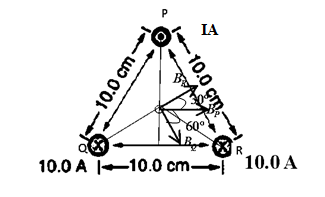
The resultant of vector
Now the net magnetic field at the centroid is
We want zero field at centroid. So,
Or
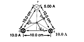
We are getting negative sign because what we have assumed the direction of current in wire P is not right to get zero field at centroid. So the new direction of current in top wire is to be into the page and its magnitude is
Conclusion:
Current in the top wire to produce a field of zero at the point equidistant from the wires is
Want to see more full solutions like this?
Chapter 22 Solutions
College Physics


- For number 11 please sketch the harmonic on graphing paper.arrow_forward# E 94 20 13. Time a) What is the frequency of the above wave? b) What is the period? c) Highlight the second cycle d) Sketch the sine wave of the second harmonic of this wave % 7 & 5 6 7 8 * ∞ Y U 9 0 0 P 150arrow_forwardShow work using graphing paperarrow_forward
- Can someone help me answer this physics 2 questions. Thank you.arrow_forwardFour capacitors are connected as shown in the figure below. (Let C = 12.0 μF.) a C 3.00 με Hh. 6.00 με 20.0 με HE (a) Find the equivalent capacitance between points a and b. 5.92 HF (b) Calculate the charge on each capacitor, taking AV ab = 16.0 V. 20.0 uF capacitor 94.7 6.00 uF capacitor 67.6 32.14 3.00 µF capacitor capacitor C ☑ με με The 3 µF and 12.0 uF capacitors are in series and that combination is in parallel with the 6 μF capacitor. What quantity is the same for capacitors in parallel? μC 32.14 ☑ You are correct that the charge on this capacitor will be the same as the charge on the 3 μF capacitor. μCarrow_forwardIn the pivot assignment, we observed waves moving on a string stretched by hanging weights. We noticed that certain frequencies produced standing waves. One such situation is shown below: 0 ст Direct Measurement ©2015 Peter Bohacek I. 20 0 cm 10 20 30 40 50 60 70 80 90 100 Which Harmonic is this? Do NOT include units! What is the wavelength of this wave in cm with only no decimal places? If the speed of this wave is 2500 cm/s, what is the frequency of this harmonic (in Hz, with NO decimal places)?arrow_forward
- Four capacitors are connected as shown in the figure below. (Let C = 12.0 µF.) A circuit consists of four capacitors. It begins at point a before the wire splits in two directions. On the upper split, there is a capacitor C followed by a 3.00 µF capacitor. On the lower split, there is a 6.00 µF capacitor. The two splits reconnect and are followed by a 20.0 µF capacitor, which is then followed by point b. (a) Find the equivalent capacitance between points a and b. µF(b) Calculate the charge on each capacitor, taking ΔVab = 16.0 V. 20.0 µF capacitor µC 6.00 µF capacitor µC 3.00 µF capacitor µC capacitor C µCarrow_forwardTwo conductors having net charges of +14.0 µC and -14.0 µC have a potential difference of 14.0 V between them. (a) Determine the capacitance of the system. F (b) What is the potential difference between the two conductors if the charges on each are increased to +196.0 µC and -196.0 µC? Varrow_forwardPlease see the attached image and answer the set of questions with proof.arrow_forward
- How, Please type the whole transcript correctly using comma and periods as needed. I have uploaded the picture of a video on YouTube. Thanks,arrow_forwardA spectra is a graph that has amplitude on the Y-axis and frequency on the X-axis. A harmonic spectra simply draws a vertical line at each frequency that a harmonic would be produced. The height of the line indicates the amplitude at which that harmonic would be produced. If the Fo of a sound is 125 Hz, please sketch a spectra (amplitude on the Y axis, frequency on the X axis) of the harmonic series up to the 4th harmonic. Include actual values on Y and X axis.arrow_forwardSketch a sign wave depicting 3 seconds of wave activity for a 5 Hz tone.arrow_forward
 Principles of Physics: A Calculus-Based TextPhysicsISBN:9781133104261Author:Raymond A. Serway, John W. JewettPublisher:Cengage Learning
 College PhysicsPhysicsISBN:9781938168000Author:Paul Peter Urone, Roger HinrichsPublisher:OpenStax College
 Physics for Scientists and Engineers, Technology ...PhysicsISBN:9781305116399Author:Raymond A. Serway, John W. JewettPublisher:Cengage Learning
 An Introduction to Physical SciencePhysicsISBN:9781305079137Author:James Shipman, Jerry D. Wilson, Charles A. Higgins, Omar TorresPublisher:Cengage Learning
 Glencoe Physics: Principles and Problems, Student...PhysicsISBN:9780078807213Author:Paul W. ZitzewitzPublisher:Glencoe/McGraw-Hill