
College Physics: A Strategic Approach (3rd Edition)
3rd Edition
ISBN: 9780321879721
Author: Randall D. Knight (Professor Emeritus), Brian Jones, Stuart Field
Publisher: PEARSON
expand_more
expand_more
format_list_bulleted
Videos
Textbook Question
Chapter 22, Problem 29P
Figure P22.29 shows the current-versus-potential-difference graph for a resistor.
Figure P22.29
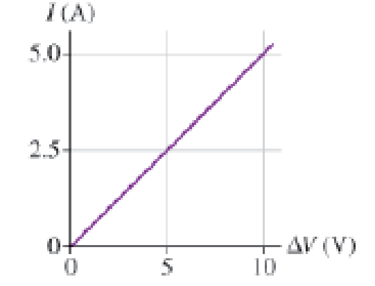
a. What is the resistance of this resistor?
b. Suppose the length of the resistor is doubled while keeping its cross section the same. (This requires doubling the amount of material the resistor is made of.) Copy the figure and add to it the current-versus-potential-difference graph for the longer resistor.
Expert Solution & Answer
Want to see the full answer?
Check out a sample textbook solution
Students have asked these similar questions
At what temperature would water boil if the outside pressure was only 19,900 Pa in degrees Celsius?
Which of these properties of a sound wave is associated with the pitch of the sound that we hear?
amplitudefrequency intensity levelintensity
A wave travels upward in a medium (vertical wave velocity). What is the direction of particle oscillation for the following?
(a)
a longitudinal wave
parallel to the direction of propagationperpendicular to the direction of propagation
Chapter 22 Solutions
College Physics: A Strategic Approach (3rd Edition)
Ch. 22 - What causes electrons to move through a wire as a...Ch. 22 - All wires in Figure Q22.519 are made of the same...Ch. 22 - A wire carries a 4 A current. What is the current...Ch. 22 - Prob. 7CQCh. 22 - Cells in the nervous system have a potential...Ch. 22 - a. Which directionclockwise or...Ch. 22 - Prob. 10CQCh. 22 - The wires in Figure Q22.11 are all made of the...Ch. 22 - The two circuits in Figure Q22.12 use identical...Ch. 22 - The two circuits in Figure Q22.13 use identical...
Ch. 22 - Rank in order, from largest to smallest, the...Ch. 22 - The circuit in Figure Q22.16 has three batteries...Ch. 22 - When lightning strikes the ground, it generates a...Ch. 22 - One way to find out if a wire has corroded is to...Ch. 22 - Over time, atoms boil off the hot filament in an...Ch. 22 - Rank in order, from largest to smallest, the...Ch. 22 - A 100 W lightbulb is brighter than a 60 W...Ch. 22 - Lightbulbs are typically rated by their power...Ch. 22 - Lightbulbs are typically rated by their power...Ch. 22 - A copper wire is stretched so that its length...Ch. 22 - The potential difference across a length of wire...Ch. 22 - A stereo amplifier creates a 5.0 V potential...Ch. 22 - A resistor connected to a 3.0 V battery dissipates...Ch. 22 - If a 1.5 V battery stores 5.0 kJ of energy (a...Ch. 22 - Figure Q22.29 shows a side view of a wire of...Ch. 22 - A person gains weight by adding fatand therefore...Ch. 22 - The current in an electric hair dryer is 10 A. How...Ch. 22 - 2.0 1013 electrons flow through a transistor in...Ch. 22 - Three wires meet at a junction. Wire 1 has a...Ch. 22 - When a nerve cell depolarizes, charge is...Ch. 22 - A wire carries a 15 A current. How many electrons...Ch. 22 - In a typical lightning strike, 2.5 C flows from...Ch. 22 - A capacitor is charged to 6.0 104 C, then...Ch. 22 - In an ionic solution, 5.0 1015 positive ions with...Ch. 22 - The starter motor of a car engine draws a current...Ch. 22 - A car battery is rated at 90 A h, meaning that it...Ch. 22 - What are the values of currents IB and IC in...Ch. 22 - The currents through several segments of a wire...Ch. 22 - How much electric potential energy does 1.0 C of...Ch. 22 - What is the emf of a battery that increases the...Ch. 22 - A 9.0 V battery supplies a 2.5 mA current to a...Ch. 22 - An individual hydrogen-oxygen fuel cell has an...Ch. 22 - An electric catfish can generate a significant...Ch. 22 - A Wire with resistance R is connected to the...Ch. 22 - Wires 1 and 2 are made of the same metal. Wire 2...Ch. 22 - Prob. 20PCh. 22 - Resistivity measurements on the leaves of corn...Ch. 22 - What is the resistance of a. A 1.0-m-long copper...Ch. 22 - A motorcyclist is making an electric vest that,...Ch. 22 - Prob. 24PCh. 22 - A 3.0 V potential difference is applied between...Ch. 22 - Prob. 26PCh. 22 - Prob. 27PCh. 22 - The aluminum wire in a high-voltage transmission...Ch. 22 - Figure P22.29 shows the...Ch. 22 - Figure P22.30 is a...Ch. 22 - In Example 22.6 the length of a 60 W, 240 ...Ch. 22 - The electric field inside a 30-cm-long copper wire...Ch. 22 - A copper wire is 1.0 mm in diameter and carries a...Ch. 22 - Two identical lightbulbs are connected in series...Ch. 22 - A 1.5 V battery moves 2000 C of charge around a...Ch. 22 - a. What is the resistance of a 1500 W (120 V) hair...Ch. 22 - Every second, a battery increases the electric...Ch. 22 - A 70 W electric blanket runs at 18 V. a. What is...Ch. 22 - A 60-cm-long heating wire is connected to a 120 V...Ch. 22 - An electric eel develops a potential difference of...Ch. 22 - The total charge a household battery can supply is...Ch. 22 - A 3.0 V battery powers a flashlight bulb that has...Ch. 22 - A heating element in a toaster dissipates 900 W...Ch. 22 - Older freezers developed a coating of ice inside...Ch. 22 - The hot dog cooker described in the chapter heats...Ch. 22 - Air isnt a perfect electric insulator, but it has...Ch. 22 - The biochemistry that takes place inside cells...Ch. 22 - High-resolution measurements have shown that an...Ch. 22 - When an ion channel opens in a cell wall (see...Ch. 22 - The total charge a battery can supply is rated in...Ch. 22 - A 1.5 V D-cell battery is rated at 15,000 mA h...Ch. 22 - The heating element of a simple heater consists of...Ch. 22 - Variations in the resistivity of blood can give...Ch. 22 - A 40 W (120 V) lightbulb has a tungsten filament...Ch. 22 - Wires arent really ideal. The voltage drop across...Ch. 22 - When the starter motor on a car is engaged, there...Ch. 22 - The electron beam inside a television picture tube...Ch. 22 - The two segments of the wire in Figure P22.59 have...Ch. 22 - A long wire used as a heating element carries a...Ch. 22 - Prob. 61GPCh. 22 - Prob. 62GPCh. 22 - Prob. 63GPCh. 22 - If resistors 1 and 2 are connected to identical...Ch. 22 - An immersion heater used to boil water for a...Ch. 22 - The graph in Figure P22.66 shows the current...Ch. 22 - Its possible to estimate the percentage of fat in...Ch. 22 - If you touch the two terminals of a power supply...Ch. 22 - The average resistivity of the human body (apart...Ch. 22 - MCAT-Style Passage Problems Lightbulb Failure...Ch. 22 - MCAT-Style Passage Problems Lightbulb Failure...Ch. 22 - MCAT-Style Passage Problems Lightbulb Failure...Ch. 22 - MCAT-Style Passage Problems Lightbulb Failure...
Additional Science Textbook Solutions
Find more solutions based on key concepts
2 Of the uterus, small intestine, spinal cord, and heart, which is/are in the dorsal body cavity?
Anatomy & Physiology (6th Edition)
Modified True/False 6. __________ Halophiles inhabit extremely saline habitats, such as the Great Salt Lake.
Microbiology with Diseases by Body System (5th Edition)
53. This reaction was monitored as a function of time:
A plot of In[A] versus time yields a straight ...
Chemistry: Structure and Properties (2nd Edition)
Why is an endospore called a resting structure? Of what advantage is an endospore to a bacterial cell?
Microbiology: An Introduction
Your bore cells, muscle cells, and skin cells look different because a. different kinds of genes are present in...
Campbell Essential Biology (7th Edition)
a. Which compound has the stretching vibration for its carbonyl group at the highest frequency: acetyl chloride...
Organic Chemistry (8th Edition)
Knowledge Booster


Learn more about
Need a deep-dive on the concept behind this application? Look no further. Learn more about this topic, physics and related others by exploring similar questions and additional content below.Similar questions
- The faster a molecule is moving in the upper atmosphere, the more likely it is to escape Earth's gravity. Given this fact, and your knowledge of rms speed, which of the following molecules can escape most easily from Earth's atmosphere if they are all at the same temperature?arrow_forwardThe temperature in one part of a flame is 2,100 K. What is the rms velocity of the carbon dioxide molecules at this temperature? Give your answer as the number of meters per second. mass of 1 mole of CO2 = 44.0 grams 1 mole contains 6.02 x 10²³ molecules the Boltzmann constant k = 1.38 x 10⁻²³ J/Karrow_forwardThe specific heat of a certain substance is 375 J/(kg°C). How much heat energy would you have to add to increase the temperature of 22 kg of this substance from 33°C up to 44°C in a number of Joules?arrow_forward
- 3.9 moles of an ideal gas are sealed in a container with volume 0.22 m3, at a pressure of 146,000 N/m2. What is the temperature of the gas in degrees Celsius?arrow_forwardwhen a cannon is launched at a 65 degree angle, will it have the same horizontal velocity as when it is launched from a 25 degree angle as long as the initial speed is the same?arrow_forwardPlease solve the problem step by step and provide explanations along each step stating what's being done. Thank you!!arrow_forward
- Figure 8.14 shows a cube at rest and a small object heading toward it. (a) Describe the directions (angle 1) at which the small object can emerge after colliding elastically with the cube. How does 1 depend on b, the so-called impact parameter? Ignore any effects that might be due to rotation after the collision, and assume that the cube is much more massive than the small object. (b) Answer the same questions if the small object instead collides with a massive sphere.arrow_forward2. A projectile is shot from a launcher at an angle 0,, with an initial velocity magnitude vo, from a point even with a tabletop. The projectile hits an apple atop a child's noggin (see Figure 1). The apple is a height y above the tabletop, and a horizontal distance x from the launcher. Set this up as a formal problem, and solve for x. That is, determine an expression for x in terms of only v₁, 0, y and g. Actually, this is quite a long expression. So, if you want, you can determine an expression for x in terms of v., 0., and time t, and determine another expression for timet (in terms of v., 0.,y and g) that you will solve and then substitute the value of t into the expression for x. Your final equation(s) will be called Equation 3 (and Equation 4).arrow_forwardDraw a phase portrait for an oscillating, damped spring.arrow_forward
arrow_back_ios
SEE MORE QUESTIONS
arrow_forward_ios
Recommended textbooks for you
 Physics for Scientists and EngineersPhysicsISBN:9781337553278Author:Raymond A. Serway, John W. JewettPublisher:Cengage Learning
 Physics for Scientists and Engineers with Modern ...PhysicsISBN:9781337553292Author:Raymond A. Serway, John W. JewettPublisher:Cengage Learning
 Principles of Physics: A Calculus-Based TextPhysicsISBN:9781133104261Author:Raymond A. Serway, John W. JewettPublisher:Cengage Learning
 Physics for Scientists and Engineers: Foundations...PhysicsISBN:9781133939146Author:Katz, Debora M.Publisher:Cengage Learning
 Physics for Scientists and Engineers, Technology ...PhysicsISBN:9781305116399Author:Raymond A. Serway, John W. JewettPublisher:Cengage Learning
Physics for Scientists and Engineers
Physics
ISBN:9781337553278
Author:Raymond A. Serway, John W. Jewett
Publisher:Cengage Learning
Physics for Scientists and Engineers with Modern ...
Physics
ISBN:9781337553292
Author:Raymond A. Serway, John W. Jewett
Publisher:Cengage Learning
Principles of Physics: A Calculus-Based Text
Physics
ISBN:9781133104261
Author:Raymond A. Serway, John W. Jewett
Publisher:Cengage Learning
Physics for Scientists and Engineers: Foundations...
Physics
ISBN:9781133939146
Author:Katz, Debora M.
Publisher:Cengage Learning
Physics for Scientists and Engineers, Technology ...
Physics
ISBN:9781305116399
Author:Raymond A. Serway, John W. Jewett
Publisher:Cengage Learning
How To Solve Any Resistors In Series and Parallel Combination Circuit Problems in Physics; Author: The Organic Chemistry Tutor;https://www.youtube.com/watch?v=eFlJy0cPbsY;License: Standard YouTube License, CC-BY